Ein riesiges Dankeschön an Jason Reilly (VK7ZJA), der leider am 17.01.2023 verstorben ist.
Er hat mir erlaubt, diese "Spiegelseiten" seiner Sammlung von Mods und Informationen zu erstellen.
(Die Übersetzung ist stellenweise etwas holprig. Dank ChatGPT)
Die originale Seite befand sich unter
http://members.optuszoo.com.au/jason.reilly1/868mods.htm
Radioddity GD-77
Tuning & alignment project
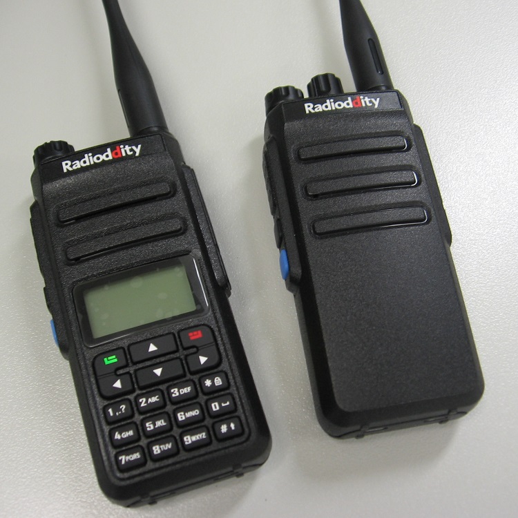
Alignment, tweaks, and flash memory corruption recovery for your Radioddity GD-77
version 2.2 --- 18th January 2022
This information is primarily intended for amateur ’ham’ radio operators who wish to maintain and adjust their GD-77. Any regulatory authority approval (e.g. FCC certification) may become invalid by the use of this information. Users should ensure their radios are operating in accordance with their licence conditions. In any case, the user alone accepts all responsibility and risk from the use of this information and tools provided here.
The Radioddity GD-77 is becoming quite a popular entry level dual band DMR handheld for amateur ’ham’ radio use. The GD-77 family takes it’s design cues from DMR radios designed for purely commercial or business two way radio usage. In that arena, should a problem develop with the equipment, the user would return the radio to their supplier for repair. The very low cost of the GD-77 means repair isn’t generally feasible, and so replacement rather than repair is the most cost effective strategy.
Ham radio operators don’t have this time/cost constraint. We often prefer to repair our own radio equipment, and have the time to experiment, tinker, and adjust the equipment until it is ’just so’ for our needs. The GD-77 tuning project was born of this philosophy. The only problem was that there were no tools, information or references to enable us to maintain the GD-77. Seeing the need for this information inspired Roger VK3KYY, Colin G4EML and Jason VK7ZJA to put the GD-77 under the microscope in order to derive the tools necessary for hams to maintain the GD-77
This information and tools have come about by deep investigation and experimentation. Radioddity have their own tuning process for the GD-77, something that is mentioned in the FCC certification documents, but is hidden from the general public in order not to reveal anything commercially sensitive. Since Radioddity don’t have a repair facility, presenting this information isn’t going to deprive Radioddity of any revenue. Indeed, the very availability of this information could improve the appeal of the GD-77 to the amateur radio community and might even result in increased sales for Radioddity, in a similar way to how MD380 Toolz must have caused an explosion of sales for TYT. I know of some ham radio operators who refuse to own any equipment for which they can’t obtain service manuals or other information necessary to maintain that equipment.
In order for you to read, change and write tuning data to the GD-77, a tool called Flash Manager has been produced.
CAUTION: The GD-77 Flash Manager software is a very low level tool and can cause serious and unrecoverable damage to your radio. Indiscriminate use can ruin both the software and hardware of your radio. Make sure you understand exactly what it is you are doing, and use with care.
Download links:
Download GD-77 Flash Manager here (61kb)
If you need a good hex editor, download HxD in your preferred language here (about 860kb)
There are four types of memory in the GD-77:
1) EEPROM 64kbyte: half of the codeplug is stored here.
2) External flash memory 1Mbyte: the other half of the codeplug, DMR IDs written by ActiveClient.exe, RF alignment data and even display character font data is stored here.
3) Internal MCU flash memory 512kbyte: this is where the radio firmware lives.
4) Internal MCU RAM 128kbyte: used by the MCU for it’s own internal operational use.
The GD-77 Flash Manager operates with the external flash memory. All 1Mbyte (8Mbits) of this flash memory are readable and almost all of the flash memory is writeable with this tool. Flash Manager can't correctly read or write any data to flash addresses 0x0000 to 0xFFFF but there is no active data stored there anyway, so this will not matter. You could edit half of the codeplug or the DMR IDs, though it would be easier to use the CPS software and ActiveClient.exe respectively to edit those.
The data of particular interest to us here is the RF alignment data. This lives in flash memory at addresses 0x08F000 to 0x08F0DF. If you are browsing other parts of flash memory, you might also find other copies of the RF alignment data at other locations, but the ’active’ data is always located at 0x08F000-0x08F0DF. Having other copies of this RF alignment data is quite handy, especially if the active data becomes corrupt. More on this later.
Your first step should be to take a backup of the entire flash memory and save it to file, so you have a copy to fall back on should something go wrong at some point. Begin by turning the GD-77 off, plug in the programming cable, and turn on the GD-77 while holding down the following key combination: side blue key, green menu button and the * (lock symbol) key. The radio will power up normally with no other unusual visible indication. This can be a tricky key sequence to get right and you might need a few attempts to successfully get this mode started up correctly.
Start up Flash Manager and carefully note the warning message, and click ’yes’ to proceed. Enter the Start address (hex) as 0, and enter the Length (hex) as 100000- that is a one and five zeroes. Click Read. You should now see the display of the GD-77 respond with ’Memory Prog’ and the top panel LED flash red, and a percentage progress bar on your PC increase. To read the entire flash will take around five and a half minutes. Then Save File and give it a .bin extension, and keep the file somewhere safe. If the file is filled with all 00s then it means the radio didn’t start up in the flash reading mode properly, and you should try the side blue key, green menu button and the * (lock symbol) power up key sequence again.
In order to begin changing parameters, refer to the table below that displays what byte (or bits) at each address in flash is used for. When altering these values, you need to keep in mind that flash memory is not like EEPROM, you can’t just overwrite data. The data you are changing first needs to be erased. Flash memory can be erased in 4, 32 or 64kbyte blocks. The GD-77 firmware performs a 64kbyte block erase for this area of flash, which means if you want to change just one byte, the flash memory will erase that 64kbyte block and you’ll need to re-write that 64kbyte entirely. With that in mind, your first step is to read the 64kbyte block of data that contains the RF alignment data. As above, put the GD-77 into the special flash read/write mode with the following power up sequence:
Blue side button + green menu button + * (lock) button held down while powering up the radio.
Begin reading at address 80000 (hex) and read for 10000 (hex) bytes. Save this block of data to a file if you like. Scroll down to address 8F000 and you should see data beginning with bytes A0 0F C0 12 A0 0F C0 12. Change the parameter you want, then write the data, again using 80000 as the start address and 10000 as the length. Each read or write for this 64kbyte block will take around 25 seconds to complete.
There are a few handy features in the Flash Manager to assist you manipulate the data:
Ctrl-F is a find feature, where you can search for data from the cursors present position onwards. Hex or ASCII strings can be searched for. F3 will find the next occurrence.
Ctrl-G will go to an address that you specify in hex, which can save a lot of scrolling in large fields of memory displays.
Alt-F12will make visible three new buttons to read, adjust and write calibration data. The adjust calibration button will give an easy interface to adjust RF tuning parameters without having to edit raw hex data. Be aware this feature is still under development and may not work completely as intended.
SERIOUS WARNING: carelessly altering certain parameters can be hazardous to your radio. For example, setting RF output power to a level significantly higher than what is already calibrated for your individual radio might well give increased RF output, but it will also dramatically increase the risk of RF PA burnout. Altering DMR I&Q parameters will definitely cause your DMR transmitted signal to become corrupted.
YOUR USE OF THIS INFORMATION AND TOOLS PROVIDED IS ENTIRELY AT YOUR OWN RISK.
| Address in flash memory | Typical value | Usage | Notes |
|---|---|---|---|
| UHF SECTION | |||
| 8F000 | A0 | Not known, must be set to this value for UHF transmitter to work | CRITICAL VALUE |
| 8F001 | 0F | Not known, must be set to this value for UHF transmitter to work | CRITICAL VALUE |
| 8F002 | C0 | Not known, must be set to this value for UHF transmitter to work | CRITICAL VALUE |
| 8F003 | 12 | Not known, must be set to this value for UHF transmitter to work | CRITICAL VALUE |
| 8F004 | A0 | Not known, must be set to this value for UHF transmitter to work | CRITICAL VALUE |
| 8F005 | 0F | Not known, must be set to this value for UHF transmitter to work | CRITICAL VALUE |
| 8F006 | C0 | Not known, must be set to this value for UHF transmitter to work | CRITICAL VALUE |
| 8F007 | 12 | Not known, must be set to this value for UHF transmitter to work | CRITICAL VALUE |
| 8F008 | E8 | DAC word for frequency reference oscillator at UHF, fine tune. | CRITICAL VALUE, typical range DC-E9 |
| 8F009 | 03 | DAC word for frequency reference oscillator at UHF, coarse tuning. Should be no need to adjust this away from value 03. | CRITICAL VALUE |
| 8F00A | E9 | Frequency fine tune for DMR mode only, UHF | CRITICAL VALUE, typically same as 8F008 or +1 of that value |
| 8F00B | 83 | Low RF power output setting, UHF freq 400 MHz | 00=lower power, FF=higher power, typical low power value ranges 65-80 |
| 8F00C | C6 | High RF power output setting, UHF freq 400 MHz | Typical high power value ranges AA-DB CAUTION: Excessively high settings will burn out electronics |
| 8F00D | 82 | Low RF power output setting, UHF freq 405 MHz | Suggestion: lower value to 40 hex gives about 30mW output, value of 20 gives no detectable output. |
| 8F00E | C5 | High RF power output setting, UHF freq 405 MHz | CAUTION: Excessively high settings will burn out electronics |
| 8F00F | 81 | Low RF power output setting, UHF freq 410 MHz | |
| 8F010 | C6 | High RF power output setting, UHF freq 410 MHz | CAUTION: Excessively high settings will burn out electronics |
| 8F011 | 81 | Low RF power output setting, UHF freq 415 MHz | |
| 8F012 | C7 | High RF power output setting, UHF freq 415 MHz | CAUTION: Excessively high settings will burn out electronics |
| 8F013 | 80 | Low RF power output setting, UHF freq 420 MHz | |
| 8F014 | C9 | High RF power output setting, UHF freq 420 MHz | CAUTION: Excessively high settings will burn out electronics |
| 8F015 | 80 | Low RF power output setting, UHF freq 425 MHz | |
| 8F016 | CA | High RF power output setting, UHF freq 425 MHz | CAUTION: Excessively high settings will burn out electronics |
| 8F017 | 81 | Low RF power output setting, UHF freq 430 MHz | |
| 8F018 | CB | High RF power output setting, UHF freq 430 MHz | CAUTION: Excessively high settings will burn out electronics |
| 8F019 | 81 | Low RF power output setting, UHF freq 435 MHz | |
| 8F01A | CB | High RF power output setting, UHF freq 435 MHz | CAUTION: Excessively high settings will burn out electronics |
| 8F01B | 81 | Low RF power output setting, UHF freq 440 MHz | |
| 8F01C | C8 | High RF power output setting, UHF freq 440 MHz | CAUTION: Excessively high settings will burn out electronics |
| 8F01D | 81 | Low RF power output setting, UHF freq 445 MHz | |
| 8F01E | C6 | High RF power output setting, UHF freq 445 MHz | CAUTION: Excessively high settings will burn out electronics |
| 8F01F | 81 | Low RF power output setting, UHF freq 450 MHz | |
| 8F020 | C5 | High RF power output setting, UHF freq 450 MHz | CAUTION: Excessively high settings will burn out electronics |
| 8F021 | 81 | Low RF power output setting, UHF freq 455 MHz | |
| 8F022 | C5 | High RF power output setting, UHF freq 455 MHz | CAUTION: Excessively high settings will burn out electronics |
| 8F023 | 7F | Low RF power output setting, UHF freq 460 MHz | |
| 8F024 | C4 | High RF power output setting, UHF freq 460 MHz | CAUTION: Excessively high settings will burn out electronics |
| 8F025 | 7E | Low RF power output setting, UHF freq 465 MHz | |
| 8F026 | C6 | High RF power output setting, UHF freq 465 MHz | CAUTION: Excessively high settings will burn out electronics |
| 8F027 | 7D | Low RF power output setting, UHF freq 470 MHz | |
| 8F028 | C6 | High RF power output setting, UHF freq 470 MHz | CAUTION: Excessively high settings will burn out electronics |
| 8F029 | 7D | Low RF power output setting, UHF freq 475 MHz | |
| 8F02A | C6 | High RF power output setting, UHF freq 475 MHz | CAUTION: Excessively high settings will burn out electronics |
| 8F02B | 3D | Unknown | |
| 8F02C | 3B | Unknown | |
| 8F02D | 3A | Unknown | |
| 8F02E | 38 | Unknown | |
| 8F02F | 37 | Unknown | |
| 8F030 | 36 | Unknown | |
| 8F031 | 35 | Unknown | |
| 8F032 | A9 | Unknown | |
| 8F033 | 1D | Unknown | |
| 8F034 | 0D | Unknown | |
| 8F035 | 0D | Unknown | |
| 8F036 | 11 | Unknown | |
| 8F037 | 11 | Unknown | |
| 8F038 | 0B | Unknown | |
| 8F039 | 0B | Unknown | |
| 8F03A | 0F | Unknown | |
| 8F03B | 00 | Unknown | |
| 8F03C | 00 | Unknown | |
| 8F03D | 00 | Unknown | |
| 8F03E | 00 | Unknown | |
| 8F03F | 18 | Unknown | CRITICAL VALUE range typically 17-1E |
| 8F040 | 16 | Unknown | CRITICAL VALUE range typically 15-1C |
| 8F041 | 14 | Unknown | CRITICAL VALUE range typically 14-1C |
| 8F042 | 13 | Unknown | CRITICAL VALUE range typically 13-1C |
| 8F043 | 16 | Unknown | CRITICAL VALUE range typically 16-1C |
| 8F044 | 14 | Unknown | CRITICAL VALUE range typically 14-1D |
| 8F045 | 15 | Unknown | CRITICAL VALUE range typically 14-1D |
| 8F046 | 12 | Squelch sensitivity gain. Lower value=more sensitive squelch. Do not go below value 08. | |
| 8F047 | 3E | UHF Mute strict, wideband, close | Higher value=lower RF level / more sensitive. NB: Strict and normal values interact somewhat |
| 8F048 | 3C | UHF Mute strict, wideband, open | |
| 8F049 | 3E | Unknown | |
| 8F04A | 3A | Unknown | |
| 8F04B | 53 | UHF Mute normal, wideband, close | |
| 8F04C | 51 | UHF Mute normal, wideband, open | |
| 8F04D | 34 | UHF Mute strict, narrowband, close | Higher value=lower RF level / more sensitive. NB: Strict and normal values interact somewhat |
| 8F04E | 32 | UHF Mute strict, narrowband, open | |
| 8F04F | 34 | Unknown | |
| 8F050 | 32 | Unknown | |
| 8F051 | 53 | UHF Mute normal, narrowband, close | |
| 8F052 | 51 | UHF Mute normal, narrowband, open | |
| 8F053 | 1C | UHF Received signal meter, low end | Suggestion: leave as is |
| 8F054 | 20 | UHF Received signal meter, high end | Suggestion: set to 60 for more realistic RSSI indication. 1 bar= -113dBm, 2 bars= -95dBm, 3 bars= -80dBm |
| 8F055 | 3C | UHF 405 MHz DMR TX 4FSK | CRITICAL VALUE Don’t adjust, typical range 3C-41 |
| 8F056 | 3A | UHF 415 MHz DMR TX 4FSK | CRITICAL VALUE Don’t adjust, typical range 3A-40 |
| 8F057 | 39 | UHF 425 MHz DMR TX 4FSK | CRITICAL VALUE Don’t adjust, typical range 39-3E |
| 8F058 | 38 | UHF 435 MHz DMR TX 4FSK | CRITICAL VALUE Don’t adjust, typical range 37-3D |
| 8F059 | 36 | UHF 445 MHz DMR TX 4FSK | CRITICAL VALUE Don’t adjust, typical range 36-3C |
| 8F05A | 35 | UHF 455 MHz DMR TX 4FSK | CRITICAL VALUE Don’t adjust, typical range 35-3A |
| 8F05B | 34 | UHF 465 MHz DMR TX 4FSK/td> | CRITICAL VALUE Don’t adjust, typical range 34-39 |
| 8F05C | 33 | UHF 475 MHz DMR TX 4FSK | CRITICAL VALUE Don’t adjust, typical range 33-38 |
| 8F05D | 1D | UHF DMR receive audio gain & beep volumes (not independantly adjustable) | Higher value=more gain |
| 8F05E | 0F | UHF TX DTMF deviation | Higher value=more deviation |
| 8F05F | 0D | UHF TX 1750Hz tone burst deviation | Higher value=more deviation |
| 8F060 | 11 | UHF TX CTCSS deviation, wideband | Higher value=more deviation |
| 8F061 | 11 | UHF TX CTCSS deviation, narrowband | Higher value=more deviation |
| 8F062 | 0B | UHF TX DCS deviation, wideband | Higher value=more deviation |
| 8F063 | 0B | UHF TX DCS deviation, narrowband | Higher value=more deviation |
| 8F064 | 0F | Unknown, but do not adjust - affects both RF power out and modulation in all modes | CRITICAL VALUE Do not adjust |
| 8F065 | 0E | Unknown, but do not adjust - affects both RF power out and modulation in all modes | CRITICAL VALUE Do not adjust |
| 8F066 | 31 | UHF analogue only mic gain (both wide & narrow band) do not exceed value 7F | Higher value=more gain |
| 8F067 | 05 | Unknown | |
| 8F068 | 27 | UHF analog overall (CTCSS, DCS, DTMF & voice) deviation, wideband, fine setting | Higher value=more deviation |
| 8F069 | 00 | UHF analog overall (CTCSS, DCS, DTMF & voice) deviation, wideband coarse setting. Should be no need to set above 00 | Higher value=more deviation |
| 8F06A | 27 | UHF analog overall (CTCSS, DCS, DTMF & voice) deviation, narrowband, fine setting | Higher value=more deviation |
| 8F06B | 00 | UHF analog overall (CTCSS, DCS, DTMF & voice) deviation, narrowband coarse setting. Should be no need to set above 00 | Higher value=more deviation |
| 8F06C | 0F | UHF analog only receive audio gain. Valid range 00 to 0F. | 8F06C & 8F06D are added to give total gain value |
| 8F06D | 0E | UHF analog only receive audio gain. Valid range 00 to 0F. | Higher value=more gain |
| 8F06E | 00 | Unknown | |
| 8F06F | 00 | Unknown | |
| VHF SECTION | |||
| 8F070 | 50 | Not known, must be set to this value for VHF transmitter to work | CRITICAL VALUE |
| 8F071 | 05 | Not known, must be set to this value for VHF transmitter to work | CRITICAL VALUE |
| 8F072 | CC | Not known, must be set to this value for VHF transmitter to work | CRITICAL VALUE |
| 8F073 | 06 | Not known, must be set to this value for VHF transmitter to work | CRITICAL VALUE |
| 8F074 | 50 | Not known, must be set to this value for VHF transmitter to work | CRITICAL VALUE |
| 8F075 | 05 | Not known, must be set to this value for VHF transmitter to work | CRITICAL VALUE |
| 8F076 | CC | Not known, must be set to this value for VHF transmitter to work | CRITICAL VALUE |
| 8F077 | 06 | Not known, must be set to this value for VHF transmitter to work | CRITICAL VALUE |
| 8F078 | EB | DAC word for frequency reference oscillator at VHF, fine tune. | CRITICAL VALUE, typical range E0-EB |
| 8F079 | 03 | DAC word for frequency reference oscillator at VHF, coarse tuning. Should be no need to adjust this away from value 03. | CRITICAL VALUE |
| 8F07A | EE | Frequency fine tune for DMR mode only, VHF | CRITICAL VALUE, typical range E4-EC |
| 8F07B | 40 | Low RF power output setting, VHF freq 136 MHz | 00=lower power, FF=higher power, typical low power value ranges 33-64 |
| 8F07C | AA | High RF power output setting, VHF freq 136 MHz | Typical high power value ranges 8B-F0 CAUTION: Excessively high settings will burn out electronics |
| 8F07D | 41 | Low RF power output setting, VHF freq 140 MHz | Suggestion: lower value to 40 hex gives about 125mW output, value of 20 gives no detectable output. |
| 8F07E | BD | High RF power output setting, VHF freq 140 MHz | CAUTION: Excessively high settings will burn out electronics |
| 8F07F | 4E | Low RF power output setting, VHF freq 145 MHz | |
| 8F080 | BE | High RF power output setting, VHF freq 145 MHz | CAUTION: Excessively high settings will burn out electronics |
| 8F081 | 55 | Low RF power output setting, VHF freq 150 MHz | |
| 8F082 | B6 | High RF power output setting, VHF freq 150 MHz | CAUTION: Excessively high settings will burn out electronics |
| 8F083 | 56 | Low RF power output setting, VHF freq 155 MHz | |
| 8F084 | B1 | High RF power output setting, VHF freq 155 MHz | CAUTION: Excessively high settings will burn out electronics |
| 8F085 | 56 | Low RF power output setting, VHF freq 160 MHz | |
| 8F086 | B5 | High RF power output setting, VHF freq 160 MHz | CAUTION: Excessively high settings will burn out electronics |
| 8F087 | 59 | Low RF power output setting, VHF freq 165 MHz | |
| 8F088 | B8 | High RF power output setting, VHF freq 165 MHz | CAUTION: Excessively high settings will burn out electronics |
| 8F089 | 5C | Low RF power output setting, VHF freq 172 MHz | |
| 8F08A | B8 | High RF power output setting, VHF freq 172 MHz | CAUTION: Excessively high settings will burn out electronics |
| 8F08B | FF | Not applicable | |
| 8F08C | FF | Not applicable | |
| 8F08D | FF | Not applicable | |
| 8F08E | FF | Not applicable | |
| 8F08F | FF | Not applicable | |
| 8F090 | FF | Not applicable | |
| 8F091 | FF | Not applicable | |
| 8F092 | FF | Not applicable | |
| 8F093 | FF | Not applicable | |
| 8F094 | FF | Not applicable | |
| 8F095 | FF | Not applicable | |
| 8F096 | FF | Not applicable | |
| 8F097 | FF | Not applicable | |
| 8F098 | FF | Not applicable | |
| 8F099 | FF | Not applicable | |
| 8F09A | FF | Not applicable | |
| 8F09B | 40 | Unknown | |
| 8F09C | F0 | Unknown | |
| 8F09D | 40 | Unknown | |
| 8F09E | F0 | Unknown | |
| 8F09F | 40 | Unknown | |
| 8F090 | F0 | Unknown | |
| 8F0A1 | FF | Not applicable | |
| 8F0A2 | FF | Not applicable | |
| 8F0A3 | 0F | Unknown | . |
| 8F0A4 | 0F | Unknown | |
| 8F0A5 | 0F | Unknown | |
| 8F0A6 | 1B | Unknown | |
| 8F0A7 | 1B | Unknown | |
| 8F0A8 | 1B | Unknown | |
| 8F0A9 | FF | Not applicable | |
| 8F0AA | FF | Not applicable | |
| 8F0AB | 00 | Unknown | |
| 8F0AC | 00 | Unknown | |
| 8F0AD | 00 | Unknown | |
| 8F0AE | 00 | Unknown | |
| 8F0AF | 1D | Unknown | CRITICAL VALUE range typically 1D-20 |
| 8F0B0 | 1D | Unknown | CRITICAL VALUE range typically 1D-1F |
| 8F0B1 | 1D | Unknown | CRITICAL VALUE range typically 1D-1F |
| 8F0B2 | 1C | Unknown | CRITICAL VALUE range typically 1C-1F |
| 8F0B3 | 1C | Unknown | CRITICAL VALUE range typically 1C-1E |
| 8F0B4 | 1C | Unknown | CRITICAL VALUE range typically 1C-1D |
| 8F0B5 | 1B | Unknown | CRITICAL VALUE range typically 1B-1E |
| 8F0B6 | 1B | Squelch sensitivity gain. Lower value=more sensitive squelch. Do not go below value 08. | |
| 8F0B7 | 3E | VHF Mute strict, wideband, close | Higher value=lower RF level / more sensitive. NB: Strict and normal values interact somewhat |
| 8F0B8 | 3C | VHF Mute strict, wideband, open | |
| 8F0B9 | 3D | Unknown | |
| 8F0BA | 3A | Unknown | |
| 8F0BB | 53 | VHF Mute normal, wideband, close | |
| 8F0BC | 51 | VHF Mute normal, wideband, open | |
| 8F0BD | 34 | VHF Mute strict, narrowband, close | Higher value=lower RF level / more sensitive. NB: Strict and normal values interact somewhat |
| 8F0BE | 32 | VHF Mute strict, narrowband, open | |
| 8F0BF | 34 | Unknown | |
| 8F0C0 | 32 | Unknown | |
| 8F0C1 | 53 | VHF Mute normal, narrowband, close | |
| 8F0C2 | 51 | VHF Mute normal, narrowband, open | |
| 8F0C3 | 20 | VHF Received signal meter, low end | Suggestion: leave as is |
| 8F0C4 | 27 | VHF Received signal meter, high end | Suggestion: set to 5D for more realistic RSSI indication. 1 bar= -113dBm, 2 bars= -95dBm, 3 bars= -80dBm |
| 8F0C5 | B1 | VHF 136 MHz DMR TX 4FSK | CRITICAL VALUE Don’t adjust, typical range B0-C3 |
| 8F0C6 | AB | VHF 140 MHz DMR TX 4FSK | CRITICAL VALUE Don’t adjust, typical range AA-BD |
| 8F0C7 | A5 | VHF 145 MHz DMR TX 4FSK | CRITICAL VALUE Don’t adjust, typical range A4-B7 |
| 8F0C8 | A0 | VHF 150 MHz DMR TX 4FSK | CRITICAL VALUE Don’t adjust, typical range 9E-B1 |
| 8F0C9 | 9B | VHF 155 MHz DMR TX 4FSK | CRITICAL VALUE Don’t adjust, typical range 98-AB |
| 8F0CA | 95 | VHF 160 MHz DMR TX 4FSK | CRITICAL VALUE Don’t adjust, typical range 93-A5 |
| 8F0CB | 90 | VHF 165 MHz DMR TX 4FSK | CRITICAL VALUE Don’t adjust, typical range 8F-9F |
| 8F0CC | 8E | VHF 172 MHz DMR TX 4FSK | CRITICAL VALUE Don’t adjust, typical range 8A-9B |
| 8F0CD | 1D | VHF DMR receive audio gain & suspected beep volumes (not independantly adjustable) | Higher value=more gain |
| 8F0CE | 10 | VHF TX DTMF deviation | Higher value=more deviation |
| 8F0CF | 0D | VHF TX 1750 Hz tone burst deviation | Higher value=more deviation |
| 8F0D0 | 11 | VHF TX CTCSS deviation, wideband | Higher value=more deviation |
| 8F0D1 | 11 | VHF TX CTCSS deviation, narrowband | Higher value=more deviation |
| 8F0D2 | 0B | VHF TX DCS deviation, wideband | Higher value=more deviation |
| 8F0D3 | 0B | VHF TX DCS deviation, narrowband | |
| 8F0D4 | 08 | Unknown, but do not adjust - affects both RF power out and modulation in all modes | CRITICAL VALUE Do not adjust |
| 8F0D5 | 0E | Unknown, but do not adjust - affects both RF power out and modulation in all modes | CRITICAL VALUE Do not adjust |
| 8F0D6 | 31 | VHF analog only mic gain (both wide & narrow band) do not exceed value of 7F | Higher value=more gain |
| 8F0D7 | 05 | Unknown | |
| 8F0D8 | 27 | VHF analog overall (CTCSS, DCS, DTMF & voice) deviation, wideband, fine setting | Higher value=more deviation |
| 8F0D9 | 00 | VHF analog overall (CTCSS, DCS, DTMF & voice) deviation, wideband coarse setting. Should be no need to set above 00 | Higher value=more deviation |
| 8F0DA | 27 | VHF analog overall (CTCSS, DCS, DTMF & voice) deviation, narrowband, fine setting | Higher value=more deviation |
| 8F0DB | 00 | VHF analog overall (CTCSS, DCS, DTMF & voice) deviation, narrowband coarse setting. Should be no need to set above 00 | Higher value=more deviation |
| 8F0DC | 0F | VHF analog only receive audio gain. Valid range 00 to 0F. | 8F0DC & 8F0DD are added to give total gain value |
| 8F0DD | 0F | VHF analog only receive audio gain. Valid range 00 to 0F. | Higher value=more gain |
| 8F0DE | 00 | Unknown | |
| 8F0DF | 00 | Unknown |
If you manage to work out what some of the unknown use parameters do, please let me know via e-mail: vk7zja at gmail dot com
Remember, you need to work with a minimum size of 64kbyte block of data, you can’t just change a few bytes on their own. Read memory from (hex) 80000 for length (hex) 10000, then edit the parameters you want and write that entire block back to the radio.
There are three pairs of bytes that also need discussing. These three lots of vital flash memory values are located at D0000-D0001, D0B30-D0B31 and E93D0-E93D1. Do NOT change them, otherwise access to flash memory via the blue button & green menu button & * (lock) button power up sequence will be lost and the only way to recover from this is to desolder the flash memory IC and program it externally.
RECOVERY FROM DATA CORRUPTION AFTER MEMORY / FACTORY RESETTING
Memory and / or factory resetting the GD-77 with certain versions of firmware, specifically between 2.6.7 and 3.1.1 (with 3.0.6 and 3.1.1 being the most common) can corrupt information in the RF alignment data block at address 8F000 onward. Typical symptoms are very low or no RF output from the radio, in either analogue FM or digital DMR modes.
Previously some users have been able to recover from this corruption by downgrading to earlier firmware versions and then performing a memory reset and re-upgrading again. This may or may not work for more recent firmware versions, reports of success vary from user to user, and I suspect it may have something to do with pre-existing conditions within the flash memory.
Described here is a method of restoring the corruption, which is both more reliable and quicker than the previous downgrade-reset-upgrade method of recovery.
As always, use these tools and information with caution, as serious damage can result from careless use.
Step 1: Download Flash Manager, and if you don’t already have a hex editor, download and install HxD. Download links are given above.
Step 2: Turn off the corrupted GD-77, connect programming cable to the radio and to the PC. Do not turn on the GD-77 yet.
Step 3: Hold down the side blue key, green menu key (above left arrow button) and the * / lock key (just below the right arrow button) while turning on the GD-77. The radio will appear to power up normally.
Step 4: Launch Flash Manager.
Step 5: Read the entire flash. Set Start address (hex) to 0, and set Length (hex) to 100000 - that’s one followed by five zeroes. Click the Read button, and wait about 5-6 minutes for the read to complete.
Step 6: Export the read data to a file using the Save File button. Call the file something like corruptGD77.bin In Windows the file should show as being 1.0 Mbyte in size.
Step 7: Launch HxD or your favourite hex editor. Open the file you just saved from Flash Manager.
Step 8: Now search for other copies of RF alignment data that should be hiding in other locations of the dump of flash memory. We are relying on the fact that some RF alignment data never changes from radio to radio. One such item of data shows up as an ASCII string of SQ4242 (note upper case / capital letters SQ). So perform a search from the beginning, looking for the ASCII string SQ4242
Step 9: Once you’ve found this occurrence, look at the data around it. About 75 (decimal) bytes prior to this SQ4242 sequence, there should be a set of repeating bytes A0 0F C0 12 A0 0F C0 12. If you do find this, then you have very likely found a valid and uncorrupted copy of your radios RF alignment data. If you don’t find this, continue searching until you do find valid RF alignment data. A common address to find such data is typically 50100 to 501DF (hex)
Step 10: From the start of the sequence of bytes A0 0F C0 12 A0 0F C0 12, copy a block of 224 bytes. So if you do find valid alignment data starting at address 50100, copy the data from address 50100 to 501DF, and paste that data into address beginning at 8F000. You can highlight, copy and paste in HxD which is very handy.
Step 11: Once you’re satisfied that you have valid RF alignment data copied over to address 8F000 to 8F0DF, save the file to disk, calling it something like repairedGD77.bin Again, the file should show as being 1.0 Mbyte in size under Windows.
Step 12: Back in Flash Manager, use the Open File button to load your repairedGD77.bin file. Scroll down to, or use the Ctrl-G feature to jump directly to address 8F000 and confirm that valid RF alignment data is present. As above, it will begin with bytes A0 0F C0 12 A0 0F C0 12. If it does not appear there, something has not gone quite right and you should go back to step 7 above and try again.
Step 13: Turn off your GD-77 and power it back on with the special power up sequence again, same as step 3.
Step 14: Now it is time to write the valid RF alignment data back to the radio. We don’t need to write the entire flash contents, but do need to write at least a 64kbyte block for this to work. Enter Start address (hex) of 80000 - that’s eight followed by four zeroes, and enter Length (hex) as 10000 - that’s one followed by four zeroes. Click Write and wait about 25 seconds for the write to complete.
Step 15: Turn off your GD-77, remove the programming cable, and power on normally, and test. Your GD-77 should be working nominally now.
It is not recommended to use the typical values in the table above to reconstruct a new RF alignment data block from scratch unless used as a last resort. The reason for this is that some parameters can be quite critical, especially the frequency tuning and DMR 4FSK values. It is always best to find copies of the RF alignment data that is specific and unique to your radio. The typical values are given as a guide only and give some context to potential adjustments you may wish to make.
© Copyright Jason Reilly, 2018-2022
Ein riesiges Dankeschön an Jason Reilly (VK7ZJA), der leider am 17.01.2023 verstorben ist.
Er hat mir erlaubt, diese "Spiegelseiten" seiner Sammlung von Mods und Informationen zu erstellen.
Die originale Seite befand sich unter
http://members.optuszoo.com.au/jason.reilly1/868mods.htm