A huge thank you to Jason Reilly (VK7ZJA) who passed away on 01/17/2023
He allowed me to create this "mirror pages" of his collection of
mods and information.
The original Page was located at
http://members.optuszoo.com.au/jason.reilly1/868mods.htm
Modifications, hints, tips and technical information for the
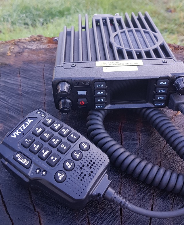
AnyTone AT-D578UV
dual / tri band DMR digital mobile radio
(Some relevance to Alinco DR-MD500 & DR-MD520 too)
Version 7.4 --- 20 October 2022
Updates made since the previous version are shown in this purple colour
This information is primarily intended for amateur ’ham’ radio operators who wish to maintain and adjust their AT-D578UV. Any regulatory authority approval (e.g. FCC certification) may become invalid by the use of this information. Users should always ensure that they and their radios are operating in accordance with their licence conditions. Many of these mods may also invalidate any manufacturer warranty you may have. In any case, the user alone accepts all responsibility and risk from the use of this information and tools provided here.
Page Index
- Introduction
- Band Error and five ways you can fix it
- What is the difference between the AnyTone AT-D578UV and AT-D878UV?
- What is the difference between the AnyTone AT-D578UV and Alinco DR-MD500 / DR-MD520?
- Hint when using the programming software / CPS
- Virus detected! Is the CPS software really safe to use?
- Hint when using the microphone
- Hints & tips for upgrading firmware
- Trouble getting the drivers to install or work properly on Win 7 or 10
- Strange error messages --- Band Error has it’s own section, click here
- A website with lots of great hints & tips for the AnyTone DMR radio family
- Looking for a guide on how to setup APRS? This website shows you how
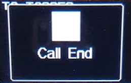
- How to reply on an active channel found while scanning
- How do I reset the radio?
- Compatibility of encryption
- A remote mount head / display for the 578?
- Bluetooth microphones and the 578
- Custom engraved call sign labels for your radio
- Differences between the two external speaker sockets
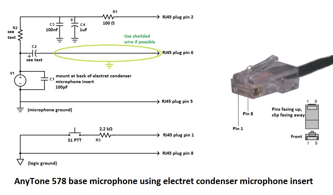
- Microphone socket pinouts & information, including use of a base microphone for your 578 or MD520, with schematic
- An integrated power supply & console is available for the 578
- Modify the 578 microphone for external audio input and output for SignaLink etc.
- Using a Bluetooth module for external audio input and output for digital modes etc.
- Hint when using a Bluetooth earpiece
- Custom background display files
- Using ’enhanced microphone audio’
- Make your radio sound like a Motorola, or play with some other fun tone sequences
- Using the address book to dial EchoLink nodes
- Known button held during power up sequences
- Selecting operational bands
- Expanding RX frequencies: modified firmware for 578 based on v1.16n & v2.03n & Alinco DR-MD520 v1.15 (all with an optional alternate display font) available for download
- Receiver sensitivity & transmit output power measurements
- What about fortuitous air band (118-136 MHz) reception for non PLUS models?
- Can the 578 be used as a scanner?
- My receive keeps cutting in and out on FM, can that be fixed? (updated)
- Expanding FM band frequencies 76 to 121 MHz
- Changing the display font / modifying some of the icons
- Alternate GPS icons to download (578 only)
- Enabling full test / self adjustment mode
- AnyTone Options software download
- Resetting your power on password
- Programming password lock
- FCC Part 90 approval information
- A look inside the 578
- What are the tiny backup batteries for?
- A mod to improve the output volume of the 578 internal speaker
- Replacing the SO-239 socket with an N-type socket
- Add an internal GPS antenna to the 578
- Improved cooling for the 578
- Improved receiver shielding for the 578
- General technical information New: updated information
- Flash memory structure in the 578
- Flash Utility software
- Backing up or restoring vital alignment & configuration data of your radio
- Fix a frozen during boot up AnyTone 578 or Alinco DR-MD500 & DR-MD520
- Preventing your radio from freezing / locking up and how to cure many problems
- Writing your own .CDD files
- French text help file (updated)
- Updating the SCT3258 baseband / DMR codec firmware Updated: includes latest version V2.01.07BF
- Future developments & ideas
If you have any more information or modifications that you'd like to share here, please contact me at vk7zja at gmail dot com and I will make sure you receive credit for your work, though you are welcome to remain anonymous if you wish.
17/01/2023 It is with heartfelt sadness that I inform you all that Jason passed away peacefully this morning.
If you have any more information or modifications that you'd like to share here, please contact me at jason at db1ig dot de and i will make sure you recieve credit for your work, though you are welcome to remain anonymous if you wish.
-
- Ensure that you do not have any power on password active. If you do, you must use the CPS software to remove it first.
- Download Colin G4EML AT Options version 8 (17kb) software from:
Download from this webpage here
Download via Mega
Download via Google Drive
Download via Sabercat host - Determine what band the codeplug is. Without the radio connected to the computer, open the codeplug .rdt file into the CPS software, and use menu Model then Model Information to display information about the codeplug. In the middle of the window will be ’Frequencys’ and next to that will be Mode with a number. This is your band number, write it down. Click on Cancel for now.
- Connect your radio to the computer with the programming cable now, and open AT Options software. Select your usual Com port and click Read.
- Next to Frequency, use the pull down list to select the band that matches the Mode number you wrote down earlier in step 2
- Click Write to change the radio band
- Back in the CPS programming software, you should now be able to write the codeplug .rdt file to the radio without a Band Error
Note- there is a bug in the CPS programming software: Local Information will not show the correct frequency band the radio is set to, but Model > Model Information does show the correct frequency band
Method 2: changing the band of your codeplug file to match the current band setting in your radio (also very easy)
- Download & unzip Francesco IK8JHL automated script tool (18kb) from:
Download from this webpage here
Download via Mega
Download via Google Drive
Download via Sabercat host - Make a backup copy of your codeplug .rdt file and keep it somewhere safe. This script tool will alter your codeplug file ’live’ without making any backup
- Determine what band your radio is set to: Open CPS programming software, and use menu Set > Set Initialization to clear memory contents first, then select Program > Read From Radio. You can select just ’Other Data’ to read. Let the CPS programming software read the radio contents, and once done select menu Model > Model Information. In the middle of the window will be ’Frequencys’ and next to that will be Mode with a number. This is your band number, write it down. Click on Cancel for now.
- Copy your codeplug .rdt file into the working directory for the RDT Band Conversion script tool
- Start up the script tool by executing the Convert.bat file
- Tell the script tool the name of your .rdt codeplug file, and the band number (given in HEX - the on screen menu will guide you) that you wish to convert your codeplug over to
- The tool will automatically edit your codeplug .rdt file to your desired band, and rename it to confirm the changes were made. Copy your converted codeplug .rdt file back into your regular folder where the CPS software looks for & loads it’s codeplug files
- Back in the CPS programming software, load the converted .rdt codeplug file and you should now be able to write the codeplug .rdt file to the radio without a Band Error
Note - there is a bug in the CPS programming software: Local Information will not show the correct frequency band the radio is set to, but Model > Model Information does show the correct frequency band
Note 2 - because of the batch file / script nature of this tool, expect your anti-virus software to complain about it, but it is 100% safe to use.
Method 3: changing the band of the codeplug to match the radio (requires hex editing skills)
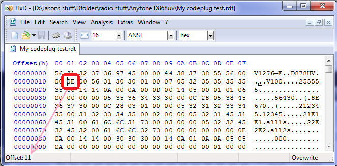
The red circle indicates byte 0x0011, which determines what band the codeplug is, change that data to 0E for band 14, or change it to 12 for band 18. Also note how the offset (address) shown in HxD indicates where your cursor is placed.
- Determine what band the radio is set to. Connect the radio to the computer with the programming cable and with the CPS programming software, read from the radio.
- In the CPS programming software use menu Model then Model Information to display information about what was read from the radio. In the middle of the window will be ’Frequencys’ and next to that will be Mode with a number. This is your band number, write it down. Click on Cancel for now and close down the CPS programming software.
- Convert the band number you wrote down into hexadecimal. As an example, if it is Mode 00015, 15=0F in hexadecimal. Write that down too.
- Now open your codeplug .rdt file in a hex editor, and look at the byte at address (hex) 0x0011. This is the byte that tells the CPS software what ’band’ the codeplug is. Change the value of the byte at address 0x0011 to the hex number you just calculated in step 3. Save the edited .rdt file under a new name.
- Start up the CPS programming software, load the edited .rdt file that you saved with a new name and send it to the radio.
- Frank, KB2MXV, has made a nice YouTube video on the process of hex-editing your band byte. He’s using a different hex editor, so it will look a little different to the above picture, but the general process is the same. Take a look at: https://youtu.be/atMWu00_33U
Method 4: when all else fails, use this export all / import all method (most reliable method, but needs the most work)
- In the CPS programming software, open your codeplug.
- Use the menu Tool then Export and look at the top of the window that opens - there is an Export All button. Click it.
- Give your export a name, and click Save. This will export all your frequencies, contacts, zones etc etc to .csv files. This could take a few minutes with no apparent progress or activity especially if your digital contact list is large, wait until an Export Complete! message is shown
- There are some settings that are not exported, such as Optional Setting information, APRS and Encryption (if you happen to be using them). Go through and write down, take screen shots or take photos of these.
- Now connect the radio to the computer with the programming cable and with the CPS programming software, read from the radio.
- Use the menu Tool then Import and look at the top of the window that opens - there is an Import From File List button. Click it.
- Find the file you saved / exported in step 3 above, and click Open. This will import all your frequencies, contacts, zones etc etc to .csv files. This step can also take a few minutes to finish, wait until the Import Complete! message is shown
- Go through the Optional Setting / APRS / Encryption settings and restore all your settings as they were before, referring to your notes, screenshots or photos from step 4 above
- Save your newly rebuilt codeplug with a new name, perhaps including the mode number in the file name for easy reference
- Now write the fully rebuilt codeplug to the radio
Method 5: change radio bands to match codeplug via radio Test Mode menus (if enabled)
- Turn off the radio, then while holding down P4 key & pushing in the dial knob, power up the radio. Keep holding them until you see ’TEST MODE’ on the screen, and release the keys. If this is not displayed, then this method will not work for you.
- After the radio has fully powered up, you should see MODE:000xx on the screen. If you don’t, use the up/down buttons until you do.
- Then rotate the dial knob to set a new MODE value to match the codeplug you are trying to send to the radio, and simply turn off the radio to set that value.
- After turning the radio back on normally, you should now be able to write your codeplug to the radio
What are the differences between the AnyTone AT-D578UV mobile and AT-D878UV handheld?
From a features viewpoint, the D578 has some extra functionality over and above the D878, such as:
- True 220 MHz operation, for the AT-D578UV PRO III. The 878 can only really be used for RX only in this part of the band.
- True simultaneous dual receive, even in the same band. While the 878 can display two VFOs, it’s receiver only toggles between the two quickly. The 578 has two independent receivers so you can receive two FM signals at the same time. (However, only one DMR signal can be received at a time)
- Obviously, higher RF output power, 60 watts on VHF and 45 watts on UHF
- Analogue inversion scrambling is featured on the 578
- Crossband repeater function, analog to analog, analog to DMR or DMR to DMR
- The 578 uses an external GPS antenna, which is is included if you purchase a GPS equipped model of the 578
- The 578 has more internal memory installed, so more complex features and larger digital contact list will be possible in the future
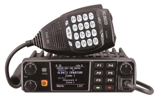
What is the difference between the AnyTone AT-D578UV and Alinco DR-MD500 / DR-MD520?
The only difference between the AnyTone AT-D578UV and Alinco DR-MD500 / DR-MD520 is that the front panel layout has changed and uses a slightly different microphone (same pinout though), otherwise all the internal electronics remain the same. The Alinco DR-MD500 is equivalent to a basic AnyTone AT-578UV dual band only, 300,000 contacts, no Bluetooth, no analog APRS RX and no AM airband, while the Alinco DR-MD520 is equivalent to the AnyTone 578 Plus model tri-band 144 / 222 / 440 MHz, 500,000 contacts, Bluetooth, analog APRS RX, and AM airband reception. You can see the some technical data relating to the Alinco DR-MD500 / MD520 at the FCC webpage if you search for FCC ID PH3DR-MD500T and PH3DR-MD520T respectively.
Hint when using the programming software / CPS
When making changes or additions in the programming software, the changes or program additions you made don’t automatically ’take’ when you close the window. You must first select the ’OK’ button then close the window. This has caught me out several times, and though it might seem obvious when reading this, it is easy enough to overlook when slaving over your keyboard.
Virus detected! Is the CPS programming software really safe to use?
Hint when using the 578 microphone
Hints & tips for upgrading firmware
Upgrading firmware on the AnyTone radio is easy, so long as you follow these general steps:
- Under the original firmware, before you do any upgrades, export everything (Tool > Export > Export All)
- Go through all your Optional Setting and write them down or take screen shots of all the settings there. If you are using encryption, also record all your encryption keys. These settings and encryption keys are not saved by the Export All process.
- Identify the correct firmware you should be using. For the AnyTone family of 578 radios, there are two different basic models: the 578 using v1.xx firmware and the 578-II using v2.xx firmware. In addition, 578s manufactured before mid-2022 use a GD32 type MCU, and those manufactured after mid 2022 will use an equivalent AT32 type MCU - and each have their own matching firmware. Look for GD or AT in the firmware file name and make sure you select the right one for your radio
- Power up the radio normally, then hold down the MENU and EXIT keys and power off the radio. Ensure the LED is flashing red, indicating firmware upload mode is active. Upload the new firmware using the CPS software menu Tool > Firmware Upgrade (if this doesn’t automatically launch a new window with the firmware updater, you can manually find and run file QX_Firmware_Update.exe which does the same thing)
- RESET the radio - this step is very important! If you do not do this, the old data in the radio could conflict with the way the firmware expects the memory to be formatted after upgrading.
- If there is a baseband update with the new firmware release, do this now. Power up the radio holding the top orange / blue button and the # button until the message "This is Boot Mode for SCT!!!" is displayed. Use a freshly installed version of the SCT_PORT Host Controller software on your PC to send the new SCT3258 hex file to the radio. Older versions of the SCT_PORT Host Controller software may not be able to load all the required information, despite giving no error or other failure indication
- If there is an icon update with the new firmware release, do this now. Power up the radio while holding in the DIAL and P1 key until the message "UPDATE MODE" is displayed. Upload the new icon file using the CPS software menu Tool > Firmware Upgrade (while this selection doesn’t specifically mention ’Icon’ this IS definitely the correct process to use) and select the icon update file to write to the radio
- Install new version CPS
- Go to Tools > Options and tick the GPS / Bluetooth / 500 Hours record / APRS options that apply to your radio.
- Now read from the freshly reset radio (yes, you are reading a ’blank’ radio, that is OK)
- Import everything saved from step 1
- Finish off your codeplug by attending to the Optional Setting & encryption keys if applicable and confirm all is correct
- Send the freshly rebuilt codeplug to the radio
- If you had a custom start up picture or background pictures, send those to the radio now
- Finally, save the codeplug and ensure you use this saved file as the basis for any further changes you may make
- Remove power from the 578 by unplugging it’s power cord, or turn off your power supply. Wait for a minute to allow things to settle
- You will need to get the help of a second person here: Hold down the POWER, MENU and EXIT buttons. While holding in those buttons, reconnect power (or turn on your power supply) and then first release just the MENU and EXIT buttons, and then release the POWER button quickly after
- If you’ve done this right, the front panel LED will be flashing red, indicating the 578 is ready to accept a firmware update. Carefully redo the firmware update again.
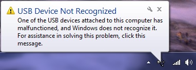
Trouble getting the drivers to install or work properly on Win 7 or 10
- If you have troubles with what Windows installs by default, create a Windows restore point first (just to be safe) and then download and update to the latest GD32 drivers here: http://www.connectsystems.com/products/top/radios/DS878UV_SOFTWARE/GD_VirtualComDriver%20v2.0.2.4944.zip (921kb) then select the x64 folder for 64 bit Windows, or x86 for 32 bit Windows operating systems
- Win 7: when Windows starts, hold F8 to get into the ’advanced boot options’ and select ’Disable Driver Signature Enforcement: Loads installed software that has invalid or missing signatures.’
- Win 10: Press and hold the shift key on your keyboard and click the Restart button. Select Troubleshoot > Advanced options > Startup Settings and then click the Restart button. When your computer restarts, you’ll see a list of options, press F7 to select Disable driver signature enforcement. Once the computer restarts, go and install the AnyTone driver.
- Out of date or invalid usbser.sys system file in c:\windows\system32\drivers folder can also cause problems. Find a new version 6.1.7601.17xxx of usbser.sys, and manually copy it into your system32 drivers folder after booting into MS DOS mode, and restart the computer.
- Some computer’s USB controllers can have trouble detecting the USB connection to the 578 if the radio is connected via it’s programming cable while turned off, then turned on after the cable is connected. If you find you have this problem, try plugging in the USB cable into the PC while your radio is powered up. Normally that’s a big no-no, as you can induce spurious transitions on the USB data lines which can lead to strange things happening. In this case it can result in a successful connection! The working theory is that it is some PC USB controllers might be too impatient waiting for the radio’s USB to respond while it is busy booting up, but if it’s already powered up the radio MCU responds quick enough to keep finicky PC USB controllers happy.
| |
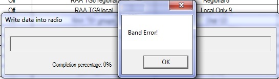
Band Error has it’s own section, click here to see five different methods on how to fix this problem. |
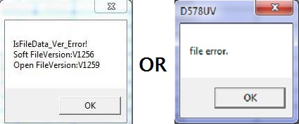 |
If you see something similar to this error message, it means you are trying to load a newer codeplug file than what your CPS software version can handle. You must make sure your CPS software version matches your codeplug file version and matches your firmware version installed in the radio and that you are using it with the correct matching model radio. |
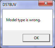 |
This error means you are trying to use the wrong CPS / wrong codeplug / wrong firmware for the model of radio you have. For example, you might be trying to use the 578 CPS with an 578-PLUS radio. You must make sure your CPS software version matches your codeplug file version and matches your firmware version installed in the radio and that you are using it with the correct matching model radio. |
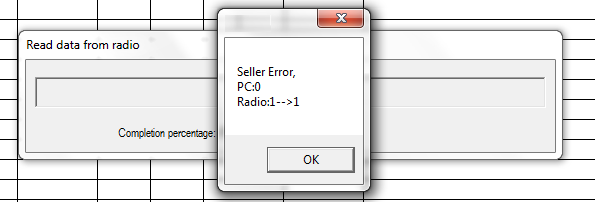 |
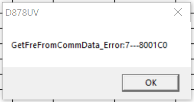
If you are getting this cryptic error message when trying to read or write to your radio, it means that your PC programming (CPS) software isn’t the same version firmware as what is on your radio. For example, in the screen grab here, this shows v1.09 software trying to interact with a radio with v1.10 firmware. You must make sure your CPS software version matches your codeplug file version and matches your firmware version installed in the radio and that you are using it with the correct matching model radio. |
 |
If you see this error, or something similar to it, this means your codeplug is corrupt. The solution is to reset the radio, REBUILD your codeplug, and write the rebuilt codeplug to your radio (thanks to Lane KD2TVW for this one) |
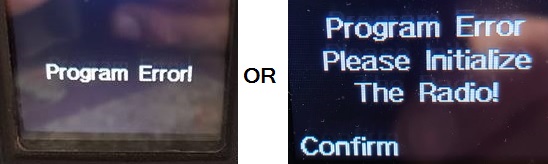 |
This error means your codeplug has become corrupt in memory. All you need do is perform a reset on the radio and reload the codeplug. I also strongly recommend doing a codeplug REBUILD before reloading it to the radio. |
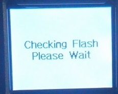 |
This error is a little more serious. A similar error message is ’Bad Block.’ Try the following, in order:
|
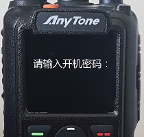 |
This message is asking you to "Please enter power on password:" in Chinese. If you know what the password is, enter it, and then you should reprogram the radio codeplug to reset the radio back in to English language. If you don’t know what the password is, you can reset it using the instructions here (yes, this is a photo of an 878, but the same error could occur on a 578 too - it will display the same) |
 |
This error, or ’RTC ERROR!’ or ’RTC not run!’ means that, for what ever reason, the radio can not read the Real Time Clock. There is a pair of tiny internal batteries, one of which backs up the Real Time Clock and keeps time when the radio is turned off. If that battery becomes too old, or goes faulty, you may see this error. If you continue to ignore this error message and the battery becomes so bad that it short circuits itself, then that could start to induce other new random errors such as the radio freezing up, not accepting any codeplug or firmware updates, and finally becoming completely unresponsive. A short circuit battery will drag down the microprocessor voltage supply, causing these random failures. The RTC backup battery can be replaced by getting access to the bottom side of the PCB and desoldering the old battery and replacing it with a new XH414HG IV01E 3 volt lithium battery. After fitting, a reset of the radio, setting the time & date and reprogramming the codeplug should set everything right. You can find out more information about the little lithium backup batteries here |
 |
Not really an error message as such, if you are seeing white blocks being displayed instead of an icon after you have made a firmware update, this means you need to also need to do an icon update to the radio. So far, the 578 has not had an icon update issued, but if you still find white squares appearing on the 578, you can use the latest 878 Icon file (it’s the same as what is used in the 578): find Icon V1.21 update download below. You send the icon .spi file to the radio by powering up the 578 in the icon update mode by holding down the DIAL and P1 buttons until UPDATE MODE is displayed. Then use the CPS menu selections Tool > Firmware Upgrade (while this selection doesn’t specifically mention ’Icon’ this IS definitely the correct process to use) and select the icon .spi file Download the 878 v1.21 icons package which uses the same icon file as the 578 (1003kb) here: Download via Mega Download via Google Drive Download via Sabercat host |
A website with lots of great hints & tips for the AnyTone DMR radio family
(Thanks to Norman M6NBP and lots of others who contributed)
If you can’t find the answer you are looking for here, then this website is a real goldmine of information. It is the accumulation of many user’s experiences, hints and tips for all of the AnyTone DMR radio family. Take a look at: http://hamradio.joomla.com/anytone-dmr.html
Looking for a guide on how to setup APRS? This website shows you how
Alex DO1ALX has created an excellent guide to setting up APRS on the AnyTone - while the guide is written for the 878, the process is the same for the 578. Take a look at his guide on doing this at:https://do1alx.de/2021/getting-analog-aprs-to-work-on-an-anytone-at-878uv-and-at-878uvii/
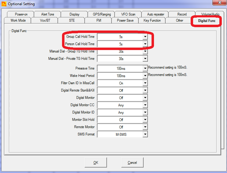
How to reply on an active channel found while scanning
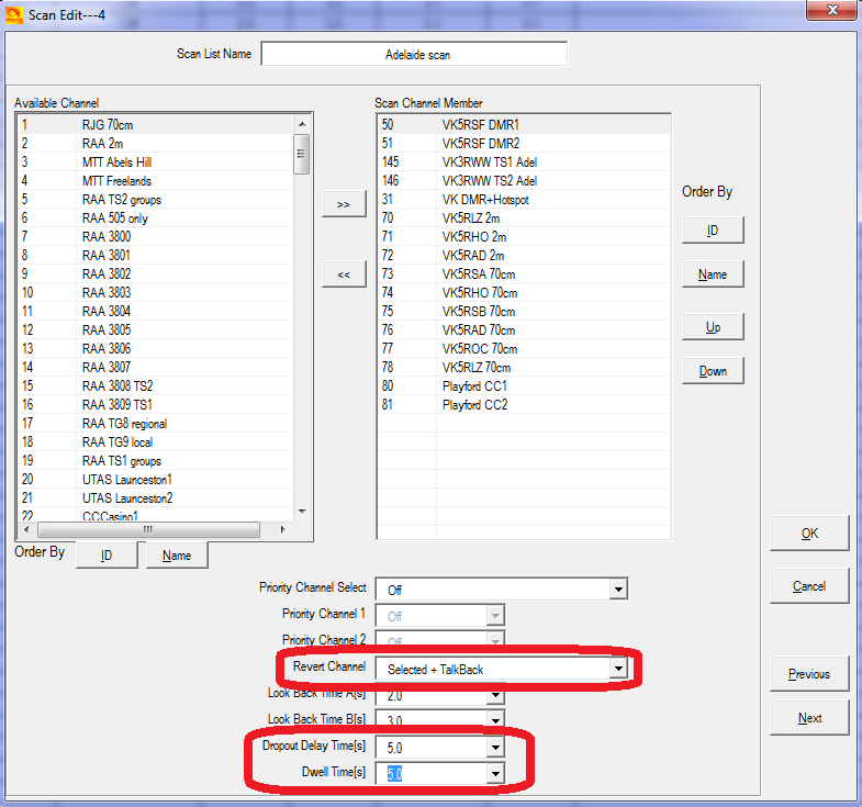
Also make sure your digital call hold times are set to 5 seconds or more:
- Ensure the radio is updated with baseband version SCT3258 V2.01.07BA or later; AES was not available on earlier versions
- Go to Options > Other > Encryption Type set to AES
- Program in the encryption keys under menu ’AES Encryption Code’ using the same key ID index (Encryption ID) and key value as other radios programmed with AES encryption
- If the key value has less than 64 hex characters, you need to pad out the key with leading zeros
- Finally, in each channel you want to encrypt, select the required key ID index number in the ’AES Digital Encryption’ setting for those channels.
- Note that SMS messages are not encrypted, so be aware of this.
The other encryption type is called ’Common’. This encryption system is set up slightly differently:
- Go to Options > Other > Encryption Type set to Common
- Program in the encryption keys under menu ’Encryption Code’ (not AES Encryption Code) using the same key value
- Finally, in each channel you want to encrypt, select ’Digital Encryption’ setting to on, and select ’Encryption TYPE’ to be the same as other radios in the communication group
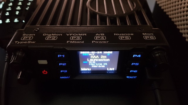
What about a remote head / display for the 578?
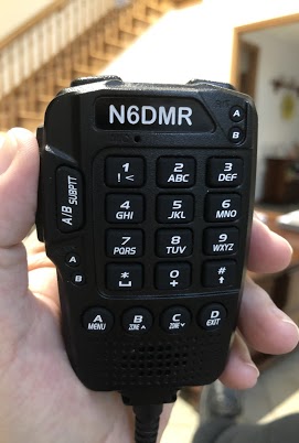
Custom engraved call sign labels for your radio
Thanks to Greg KC8GL, you can order a custom laser engraved self adhesive label for your radio that perfectly fits the AnyTone 578 microphone, at a very attractive price. Greg recommends using a black magic permanent ink marker pen to run a line of ink around the white edge of the labels to help hide the white substrate, touching off that professional look once the label is installed. Also check out the lovely cherry wood callsign display plaques that Greg does. I highly recommend them! Greg is a fantastic guy, quick to respond and happy to answer any questions you may have. See his website at: https://sites.google.com/view/kc8gl/d578uviii-pro-microphone-call-sign-sticker
Another product that Greg has will be of particular interest to 578 owners. If you have trouble remembering what all the programmed functions go with what button, this is going to be perfect for you. Now you can banish the hand scribbled sticky note you keep by the 578 to remind you of what button does what! Greg has a special web page set up for this very professional sticker at: https://sites.google.com/view/kc8gl/anytone-578-p-button-cheat-sheet
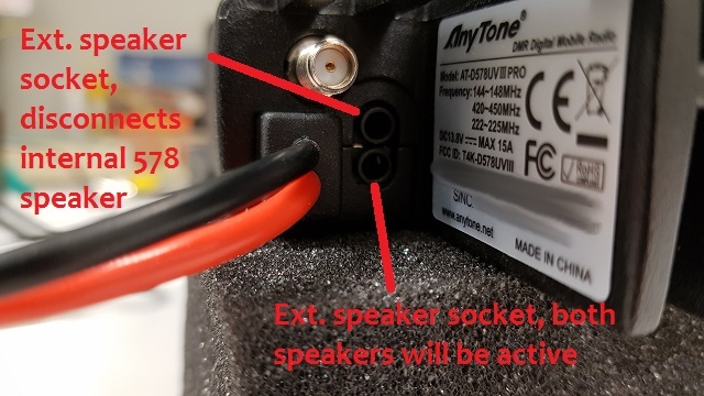
External speaker socket differences on the AT-D578UV
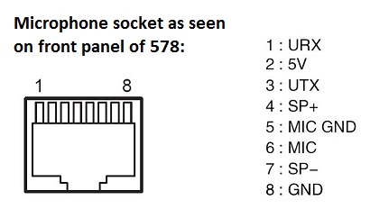
Microphone socket pinouts & information AT-D578UV and DR-MD520
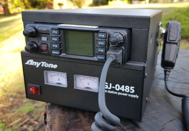
An integrated power supply & console is available for the 578
Modify the 578 microphone for external audio input and output for SignaLink etc. Moderate
With thanks to Tim N8NQH
For applications where you might want to connect external TX microphone audio and RX received audio to an external device, such as a SignaLink, TNC or RigBlaster etc. then this modification from Tim N8NQH is perfect. Read all about it at this link: http://tim-yvonne.com/ham/dmr/how-to/signalink-to-d578.htm
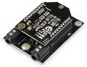
Using a Bluetooth module for external audio input and output for digital modes etc. Easy
With thanks to a ham who wished to remain anonymous
As an alternative to the above modification of the microphone for connection to a SignaLink, you can use some Bluetooth modules to get audio in and out of the 578, so you can then use digital modes etc. But apparently, many cheap USB Bluetooth adapters are not very good for this purpose. After much experimentation, one ham hit upon a nice little $12 Bluetooth module that works a treat. The TinySine Bluetooth adapter converts the Bluetooth connection to a standard pair of 3.5mm audio sockets, one for microphone in, the other for line out. Those are then connected to your PC with standard 3.5mm audio patch cables. It’s powered by a micro USB socket, but this doesn’t form the link to your PC, it is only used to power the TinySine. Easy!
There are a couple settings on the radio which you may want to change as well. Under the Bluetooth menu of the radio, there is a ’BT + int mic’ option: if turned on, you are able to use both the hand mic to talk, and the computer to send audio to the 578. There is also a ’BT + int spk’ option: you can decide if you would like to have audio come out of both the radio speaker, and out via Bluetooth going to the computer.
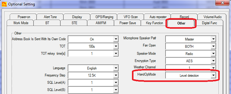
To send the radio into transmit, you must use AnyTone’s little Bluetooth PTT button. Another option is to set the HandOpMode to Level Detection (see above information on microphones ) and use whatever digital mode you are using control PTT, but you will then lose the ability to use the microphone as it must be unplugged for this option to work.
See more information about the TinySine here: https://www.tinyosshop.com/index.php?route=product/product&path=158_168&product_id=973
Hint when using a Bluetooth earpiece
Custom background display files for your AT-D578UV
Tim DL2DMC has made available some very nice looking background display files. While these are intended for the 878, they will also work on the 578 too. If you have made your own background display image and would like to share it with others, please get in touch with me by email and I will place it here for everyone.
Download from: http://www.geoo.de/AnytoneDL/D878UVscreens.zip

Chris 2E0UKH has made a video preview of these backgrounds and shows you how to upload them to the 878 - the process is practically identical for the 578 too. Take a peek at his YouTube video here: https://youtu.be/tPMhNEPVgjw
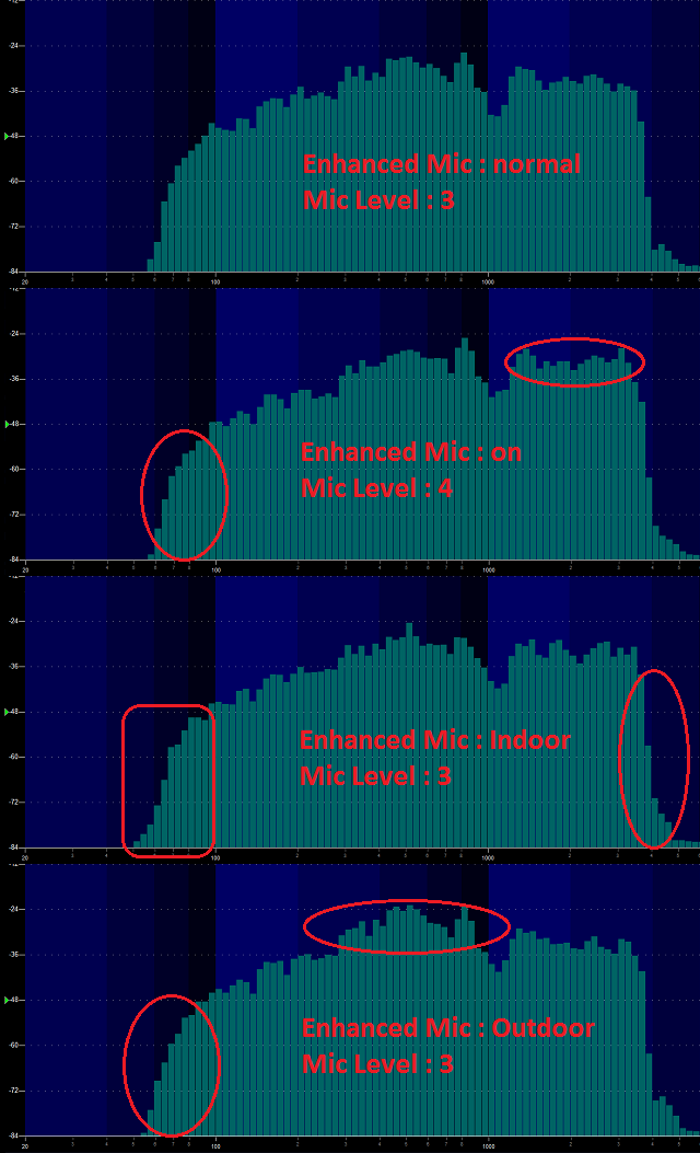
Using ’enhanced microphone audio’
- Normal - this is the standard transmit audio response
- Mic Enhance - this rolls off the low end response of the microphone, so if you have a deep and booming voice, this might make your voice a little more pleasant to listen to on DMR. Enabling Mic Enhance causes DMR transmitted audio to be overall a bit quieter, so to compensate for that, bump up your Mic Level up one notch. You could also use Mic Enhance to quieten down your DMR transmitted audio but leave FM transmitted audio level unaffected, if you find that people are telling you that you are too loud on DMR but fine on FM
- Indoor - this adds a little bit of extra emphasis at the very top and bottom end of your transmitted audio for a more relaxed, fuller sound
- Outdoor - this setting rolls off the low end response of the microphone similar to Mic Enhance, but also adds some mid range emphasis; this might be useful when using the radio in an area with increased background noise, such as in a vehicle
Make your radio sound like a Motorola
Using the address book to dial EchoLink nodes
- First, in the CPS, go to Analog > Analog Address Book and add in each node you might want to be able to quickly recall / dial. The node number goes in the Number column, and the node name / callsign goes under the Name column. This name is what you will see on the radio screen, so it can be given any name that is meaningful to you.
- Then, in Analog > DTMF Setting, set the following:
It is recommended to switch off the side tone, as otherwise you will hear the DTMF tone while transmitting, with full audio level (which could be annoyingly loud).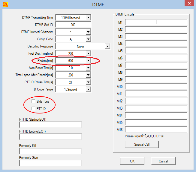
- Next, in Optional Settings > Other, set your Address Book Is Sent With Its Own Code to off.
- The final step is to go in to each channel that is programmed that you will use to connect to your local EchoLink node, and ensure that Optional Signal is set to DTMF.
Known button held during power up sequences
- Press MENU and EXIT keys together just after power OFF for main firmware update mode (red LED blinks)
- P1 and dial held down on power up enters a display icon update mode
- P2 and dial held down on power up enters the reset menu
- P3 and dial held down on power up enters a GPS module test mode
- P4 and dial held down on power up enters the TEST MODE where you can select operational bands ("modes") and/or adjust alignment parameters, but only if this has been first enabled by AT Options software
- P5 and dial held down on power up enters test mode with BHT (Bluetooth) turned on
- P6 and dial held down on power up enters an update mode for LinkBoard (Bluetooth) No updates available as yet.
- MENU and dial held down on power up enters the DSP SCT update mode
- EXIT and dial held down on power up enters a GPS signal strength (RSSI) test mode
- Mic PTT and dial held down on power up enters an update mode for Hand-Soft - to update the mini MCU running the controls of the microphone. No updates available as yet.
- Normally, test mode will be completely inhibited as delivered by the factory
- With ’band select’ test mode, you will only be able to select MODE to change operational frequency bands of the radio
- In full unlocked test mode, some degree of calibration / alignment is possible from the front panel of the radio for deviation levels, power output levels, received signal strength indication (RSSI) levels, squelch levels, frequency fine setting and more.
See the section below titled Enabling full test / self adjustment mode for more detail.
There are many different choices of bands that you can select to use, which may change depending on firmware version.
Note that whenever you do change MODE, the radio will reset and you will lose your programmed data. Make sure you have a saved copy of your codeplug. Each saved codeplug will have the MODE it was created under encoded within it. If you try to reload the same codeplug after changing MODE, the CPS software will reject it, saying that it is the wrong band. To fix this, you will need to ’hex edit’ the codeplug rdt file: change byte 0x0011 to match the MODE selected. For example, if you set MODE=00002 then edit your codeplug byte 0x0011 to be hex value 02. Or if you set MODE=00010 then set codeplug byte 0x0011 to hex value 0A.
Note- there is a bug in the CPS programming software: Local Information will not show the correct frequency band the radio is set to, but Model > Model Information does show the correct frequency band
Begin by turning the radio off, then press and hold the P4 and dial buttons down while turning on the radio, hold those two buttons until you see ’TEST MODE’ appear on screen. After releasing the buttons the radio will start up with the text ’MODE:00000’ to the bottom of the screen
If you don’t see this screen, you will need to download AT Options software and enable ’Band select’ check box & write this back to the radio. See: Download AT Options software
Rotate the top dial to change the mode number, which will select the following:
Standard MODES selectable on the AnyTone 578 (all flavours) & Alinco DR-MD500 / MD520:
| MODE | 578 v1.15 / v2.02 RX | 578 v1.15 / v2.02 TX | MD500 v1.06 RX | MD500 v1.06 TX | MD520 v1.15 RX | MD520 v1.15 TX |
|---|---|---|---|---|---|---|
| 00000 | 400-480 & 136-174 | 400-480 & 136-174 | 400-480 & 136-174 | 400-480 & 136-174 | 400-480 & 136-174 | 400-480 & 136-174 |
| 00001 | 400-480 & 136-174 (12.5k only) | 400-480 & 136-174 (12.5k only) | 400-480 & 136-174 (12.5k only) | 400-480 & 136-174 (12.5k only) | 400-480 & 136-174 (12.5k only) | 400-480 & 136-174 (12.5k only) |
| 00002 | 430-440 & 136-174 | 430-440 & 136-174 | 430-440 & 136-174 | 430-440 & 136-174 | 430-440 & 136-174 | 430-440 & 136-174 |
| 00003 | 400-480 & 136-174 | 430-440 & 144-146 | 400-480 & 136-174 | 430-440 & 144-146 | 400-480 & 136-174 | 430-440 & 144-146 |
| 00004 | 434-438 & 144-146 | 434-438 & 144-146 | 434-438 & 144-146 | 434-438 & 144-146 | 434-438 & 144-146 | 434-438 & 144-146 |
| 00005 | 434-447 & 144-146 | 434-447 & 144-146 | 434-447 & 144-146 | 434-447 & 144-146 | 434-447 & 144-146 | 434-447 & 144-146 |
| 00006 | 446-447 & 136-174 | 446-447 & 136-174 | 446-447 & 136-174 | 446-447 & 136-174 | 446-447 & 136-174 | 446-447 & 136-174 |
| 00007 | 400-480 & 136-174 | 420-450 & 144-148 | 400-480 & 136-174 | 420-450 & 144-148 | 400-480 & 220-225 & 136-174 | 420-450 & 222-225 & 144-148 |
| 00008 | 400-470 & 136-174 | 400-470 & 136-174 | 400-470 & 136-174 | 400-470 & 136-174 | 400-470 & 136-174 | 400-470 & 136-174 |
| 00009 | 430-432 & 144-146 | 430-432 & 144-146 | 430-432 & 144-146 | 430-432 & 144-146 | 430-432 & 144-146 | 430-432 & 144-146 |
| 00010 | 400-480 & 136-174 | 430-450 & 144-148 | 400-480 & 136-174 | 430-450 & 144-148 | 400-480 & 136-174 | 430-450 & 144-148 |
| 00011 | 400-520 & 136-174 | 400-520 & 136-174 | 400-520 & 136-174 | 400-520 & 136-174 | 400-520 & 136-174 | 400-520 & 136-174 |
| 00012 | 400-490 & 136-174 | 400-490 & 136-174 | 400-490 & 136-174 | 400-490 & 136-174 | 400-490 & 136-174 | 400-490 & 136-174 |
| 00013 | 400-480 & 136-174 | 403-470 & 136-174 | 400-480 & 136-174 | 403-470 & 136-174 | 400-480 & 136-174 | 403-470 & 136-174 |
| 00014* | 400-520 & 220-225 & 136-174 | 400-520 & 220-225 & 136-174 | 400-520 & 220-225 & 136-174 | 400-520 & 220-225 & 136-174 | 400-520 & 220-225 & 136-174 | 400-520 & 220-225 & 136-174 |
| 00015 | 420-520 & 144-148 | 420-520 & 144-148 | 420-520 & 144-148 | 420-520 & 144-148 | 420-520 & 144-148 | 420-520 & 144-148 |
| 00016 | 430-440 & 144-147 | 430-440 & 144-147 | 430-440 & 144-147 | 430-440 & 144-147 | 430-440 & 144-147 | 430-440 & 144-147 |
| 00017 | 430-440 & 136-174 | 136-174 only | 430-440 & 136-174 | 136-174 only | 430-440 & 136-174 | 136-174 only |
| 00018 | 400-480 & 220-225 & 136-174 | 420-450 & 222-225 & 144-148 | 400-480 & 220-225 & 136-174 | 420-450 & 222-225 & 144-148 | 400-480 & 220-225 & 136-174 | 420-450 & 222-225 & 144-148 |
The bands that are indicated in grey above are not directly selectable via the test menu MODE selection. You can use AT Options application to select one of these hidden bands if you require.
* MODE 00014 is not directly selectable, you first need to enter a password to enable this band. When MODE and the band number is displayed, press any number on the keypad and the radio will ask "INPUT PASSWORD:" if you happen to know what this password is, enter it, and then you should be able to select MODE 00014. Then turn off the radio, which will save your selected mode setting, and from that point on, your radio will use the frequency limits that correspond with the mode setting you selected. You can repeat the process to change MODES at any time.
If using AT Options to set the band, this software will automatically do what is necessary to enable MODE 00014, knowledge of the password is not needed.
Note- there is a bug in the CPS programming software: Local Information will not show the correct frequency band the radio is set to, but Model > Model Information does show the correct frequency band
I will not be sharing the password for MODE 00014 under any circumstances, as the FCC is starting to closely scrutinise these matters and we don’t them to revoke the approval status for these wonderful radios, which would result in the AnyTone radios being withdrawn from sale, then nobody would be able to enjoy them.
For the vast majority of users, there is no need to use MODE 00014 anyway. The alternate firmware files available at expanded RX frequencies with alternate firmware will permit out of band reception under any MODE selection, making MODE 00014 mostly redundant. If you have a genuine requirement for MODE 00014, then please see your dealer.
To carry out this modification do the following:
- Make sure you have downloaded the correct package for your model of radio, and unzip the contents
- Make sure you have saved your codeplug (rdt) configuration file
- Using the regular firmware updating software & process, send this frequency expanded firmware to the radio.
- If necessary, update your codeplug / rdt configuration file to be compatible with the version of firmware you have downloaded. If you want to reuse your saved codeplug rdt configuration file, you may need to modify one byte with a hex editor as detailed below
- Enjoy actual extra receive frequency coverage of around 110-281 MHz, and 339-527 MHz (varies from individual radio to radio). On the 578 Plus model only, you will also be able to use the AM Air band up to 144 MHz to cater for those countries that have special air band frequencies above 136 MHz (with thanks to Francesco IK8JHL)
Download via Mega
Download via Google Drive
Download via Sabercat host
Download the frequency expanded / modified 578-II (PLUS model with airband) firmware package (2.5 Mb) based on v2.03n firmware from:
Download via Mega
Download via Google Drive
Download via Sabercat host
Download the frequency expanded / modified DR-MD520 firmware package (1.2 Mb) based on v1.15 firmware from:
Download via Mega
Download via Google Drive
Download via Sabercat host
(Unfortunately there is no frequency expanded firmware for the DR-MD500 model at this point)
Your mileage may vary of course, due to individual radio & component manufacturing tolerances. You can use the VFO and add memory channels to use these new expanded receive frequency ranges. Note that with the expanded frequencies, you can’t enter frequencies via keypad direct entry that start with a 3 or 5 (e.g. any frequency in the 300 or 500 MHz range) the only way to get to them is via lots of knob twisting in VFO mode.
To enter out of band frequencies in the CPS programming software, you will need to use the export-edit-import method: program some dummy channels with valid but easy to recognise frequencies, for example 456 MHz, then use the export feature (tool > export > channel > give it a name > export) and save your exported channels. Open the exported channels file with a text editor - look for your dummy channels you had previously entered, and edit the frequencies as you require, and save the file. Back in the CPS software, use the import feature (tool > import > channel > find your edited csv file > import) to bring the channels with out of band edited frequencies into the radio.
Transmit remains standard according to each MODE. Note that out of band receive frequencies can be very low in sensitivity due to the excellent front end filtering of these radios.
Refer to the sensitivity plots below:
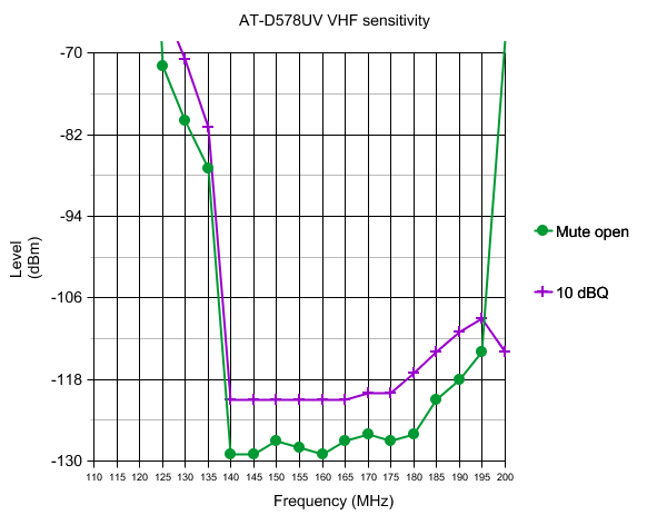
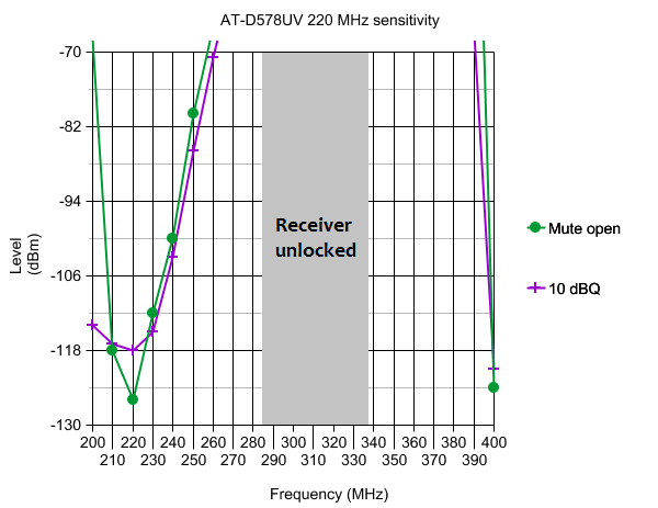
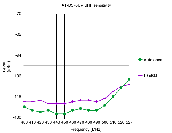
with thanks to Sergei for these measurements
| Test frequency | Low | Mid | High | Turbo |
|---|---|---|---|---|
| 145.5 MHz | 1.2 | 10 | 25 | 58 |
| 225.0 MHz | 1.5 | 6.0 | 6.0 | 6.0 |
| 435.0 MHz | 1.1 | 11 | 26 | 43 |
What about fortuitous air band (118-136 MHz) reception for non PLUS models?
Can the 578 be used as a scanner?
My receive keeps cutting in and out on FM, can that be fixed?
- Check that you have the receiver set to wideband FM (radio menus: Settings > Chan Set > Band width > Wide) which is the correct mode for listening to most ham activity in the USA and for NOAA signals.
- Turn STE settings to OFF, particularly the ’STE when no signal’ setting (CPS menu: Optional Setting > STE)
Expanding FM band frequencies 76 to 120 MHz Easy
Changing the display font / modifying some of the icons Advanced
- Download from this webpage here
- Download via Mega
- Download via Google Drive
- Download via Sabercat host
Be aware that the bitmapped icons and fonts are vertical raster, not horizontal. It could take a lot of scrolling through the file to identify the font, but the auto step feature makes life a lot easier.
In the 578 firmware, there are six font sizes: 7x10 H x W starting at 0x08CEDF; 8x8 H x W starting at 0x08CF7C; 12x12 H x W starting at 0x08D16E; 16x16 H x W starting at 0x08DA5E; 24x11 H x W starting at 0x08E641; and a super large 24x16 font starting at 0x08F376. Other symbols such as the antenna signal meter etc. will be found starting at 0x08FBC8. These addresses / locations are only valid for firmware version 1.05, the exact locations will change a little in other versions.
Once you find the location of the font you want to play with, make a note of its starting location. Now you’ll want to create a font of the same size. A very useful tool to convert fonts from your computer into bitmaps is Rays Font Editor which you can download here:
Make sure you convert the font to the same size as the one you are going to replace. To use Rays Font Editor to produce a bitmap ready for the 578:
- Install your desired TTF font as a system font on your PC
- Select Capture System Font, then select your desired font from the list
- Select input size by point, and play around with the value to get each character fully visible. Typically the letters M and W are difficult to fit width wise and get truncated at the sides, and lower case letters g, j, p, q and y can get cut off at the bottom: try smaller point values to get the font small enough to fit or manually tweak the problem letters yourself. As an example, the Courier New TTF font works well if imported at 10 point size
- Select Output character size - Change font size and enter height and width to suit the font you are replacing, and click OK
- Examine your characters that have been imported to make sure they all fit nicely and are fully legible. You can edit the appearance and shift characters up/down/left/right to make them look nice.
- Select Font settings, and choose character range starting at 32 and ending at 126, as those are the only characters the 578 needs
- Select Export font. You want to select ’custom’, format is binary file, scan direction set to start top-left, scan vertical and leave the other settings as they are. Give your font a name and save it
- Rename the extension of your font from a .dat to .bin and you have a file that’s ready to go into the 578.
Once you have a binary image of your desired font, you might want to use Colin’s ImageTest application to examine the fonts and confirm how they’ll appear on the radio screen.
Now it is simply a case of using your hex editor to copy this binary data from the file you just created over the top of the font data in the firmware file, at the start address you noted earlier. If using HxD, use paste write, not paste insert when copying your new font binary data into the firmware image. Write the firmware to your 578 and enjoy a new look display.
Multi-coloured icons, other than the basic mono-chromatic symbols, are mostly stored in the 578 flash memory locations 0x0015A000 to 0x00200000. The 578 currently uses the same icons as the latest 878, and so you can use the 878 Icon V1.21 update to write to those memory locations. As a result, if you want to play with custom icons, it is easiest to edit a copy of the 878 icon file (download links here) if you want to customise some of your coloured icons. They are encoded as RGB565 raw bitmap format, and of varying sizes. You could use a raw bitmap viewer to explore the contents of the icon update file. A good website to do this is located at: http://rawpixels.net/
For full screen bitmaps such as the start up image, select a width of 128 pixels, height of 160 pixels, select Flip V, select Predefined format of RGB565, and make sure Little Endian is not selected. For other icons you will need to play around with the width and height, but should use the same settings.
A few other coloured icons are encoded into the firmware image, the main one there being the 11x11 digital monitor speaker symbol.
Alternate GPS icons to download (578 only)

These are written to the radio using the UPDATE MODE:
- Download & unzip this alternate GPS ICON_V1.22_M1 pack (1.2Mb) from one of these locations:
Download via Mega
Download via Google Drive
Download via Sabercat host - Connect the radio to your computer with the programming cable
- Turn on the 578 while holding down DIAL & P1 buttons until UPDATE MODE is displayed
- Start up the CPS software and navigate to menus: Tool > Firmware Upgrade (while this selection doesn’t specifically mention ’Icon’ this IS definitely the correct process to use). If a new Firmware Update window doesn’t automatically open, you can manually find and launch the QX_Update_Firmware.exe to achieve this
- Select Open Update File and point the software to the new Icon pack file ICON_V1.22_M1.spi file and click write
- The update takes just over 40 seconds to write, power cycle the radio normally once finished
Enabling full test / self adjustment mode Advanced
(Credit to Colin G4EML and Jason VK7ZJA)
Warning: you can seriously mess up your radio with this adjustment mode to the point that it may not transmit, receive, or even have a visible display with careless changes to certain values. If you do not know what you are doing, leave this alone.
There is a way to enable the full test mode menu on the radio so you can not only alter the operational bands, but also things like setting Turbo, High, Mid & Low RF output power levels individually, fine tune the frequency, set the squelch sensitivity, change the received signal strength S-meter (RSSI) meter curve, even calibrate the battery voltage readout.
Begin by connecting your radio to the CPS software and take a screenshot of, or write down the information shown in the ’Local Information’ screen. This is very handy information to keep. Also ensure you have saved a copy of your current codeplug
Note- there is a bug in the CPS programming software: Local Information will not show the correct frequency band the radio is set to, but Model > Model Information does show the correct frequency band
- Download from this webpage here
- Download via Mega
- Download via Google Drive
- Download via Sabercat host
*As always, this software is provided without any warranties, and you use it entirely at your own risk. Using this application to write any changes to your radio is also likely invalidate the manufacturer’s warranty
(The application is also suitable for the AnyTone 878, 878-II & 868, Btech 6X2, Alinco DJ-MD5 & DJ-MD5X, and Alinco DR-MD500/MD520 - thanks to Jason Alexander for assistance with the Alinco models)
Ensure that you do not have any power on password active. If you do, you must use the CPS software to remove it first. Use of AT Options while a power on password is active can, under certain circumstances, cause some data to be overwritten with default data.
When you run the software, select your COM port and READ from the radio. Then edit any text fields you may want, and make sure Band Select and Full Test Mode check boxes are ticked. Finally, WRITE the settings back to the radio - this only takes a fraction of a second to do, and the radio will reboot. It may take a few extra seconds more than normal to boot up, this is OK as it is reconfiguring internal memory.
To activate test mode, turn off the radio, hold down the P4 and dial buttons while turning on the radio until TEST MODE is displayed on the radio screen (this takes a few seconds to happen), then let the two buttons go. The radio will boot up into it’s full test / self adjustment mode.
Once you start test mode, scroll up and down between different test adjustment points using the zone up/down button. The following adjustments are available:
I strongly recommend you go through each setting and write down what they are before making any adjustments \
| 578 Setting | Adj. range | Description | Typical value | |
|---|---|---|---|---|
| 1 | UHF AL | nil | A-VFO Low UHF test frequency | |
| 2 | UHF AM | nil | A-VFO Mid UHF test frequency | |
| 3 | UHF AH | nil | A-VFO High UHF test frequency | |
| 4 | VHF AL | nil | A-VFO Low VHF test frequency | |
| 5 | VHF AM | nil | A-VFO Mid VHF test frequency | |
| 6 | VHF AH | nil | A-VFO High VHF test frequency | |
| 7 | UHF BL | nil | B-VFO Low UHF test frequency | |
| 8 | UHF BM | nil | B-VFO Mid UHF test frequency | |
| 9 | UHF BH | nil | B-VFO High UHF test frequency | |
| 10 | VHF BL | nil | B-VFO Low VHF test frequency | |
| 11 | VHF BM | nil | B-VFO Mid VHF test frequency | |
| 12 | VHF BH | nil | B-VFO High VHF test frequency | |
| 13 | FQCA | 0-255 | A-VFO Frequency fine tune | 41 * |
| 14 | TXDAU | 0-255 | Unknown UHF analogue adjustment | 150 |
| 15 | PAHU | 0-255 | UHF RF power output turbo setting | 180 |
| 16 | PAMU | 0-255 | UHF RF power output high setting | 130 |
| 17 | PALU | 0-255 | UHF RF power output medium setting | 85 |
| 18 | PASU | 0-255 | UHF RF power output low setting | 25 |
| 19 | MODU | 0-255 | Overall deviation setting for UHF | 105 |
| 20 | MIC | 0-63 | Microphone gain set | 54 |
| 21 | TONEU | 0-255 | Transmit audio tone level, push PTT to transmit a test 1000 Hz tone on displayed UHF FM frequency | 98 |
| 22 | TONEV2 | 0-255 | Transmit audio tone level, push PTT to transmit a test 1000 Hz tone on displayed VHF FM frequency | 40 |
| 23 | CTCW | 0-128 | Deviation setting for CTCSS in both UHF & VHF | 39 |
| 24 | DCSW | 0-128 | Deviation setting for DCS in both UHF & VHF | 28 |
| 25 | BPFLUA | 0-255 | UHF A-VFO receive tracking gain, low end of band | 35 |
| 26 | BPFMUA | 0-255 | UHF A-VFO receive tracking gain, mid band | 135 |
| 27 | BPFHUA | 0-255 | UHF A-VFO receive tracking gain, top end of band | 253 |
| 28 | BPFLUB | 0-255 | UHF B-VFO receive tracking gain, low end of band | 35 |
| 29 | BPFMUB | 0-255 | UHF B-VFO receive tracking gain, mid band | 145 |
| 30 | BPFHUB | 0-255 | UHF B-VFO receive tracking gain, top end of band | 253 |
| 31 | AGCUA | 0-255 | UHF A-VFO AGC (suspect receiver gain related) | 180 |
| 32 | AGCUB | 0-255 | UHF B-VFO AGC (suspect receiver gain related) | 170 |
| 33 | SQTHUA | 0-255 | UHF A-VFO squelch threshold | 90 |
| 34 | SQTHUB | 0-255 | UHF B-VFO squelch threshold | 100 |
| 35 | RSSIUA | nil, only displays current value | UHF RSSI A-VFO, inject RF at desired level for 1 bar reading, rotate dial to sample and lock in value | 72 |
| 36 | RSSIUB | nil, only displays current value | UHF RSSI B-VFO, inject RF at desired level for 1 bar reading, rotate dial to sample and lock in value | 75 |
| 37 | A OBH | 0-65535 | unknown A+D adjustment | 3000 * |
| 38 | A OBL | 0-65535 | unknown A+D adjustment | 2700 * |
| 39 | D OBH | 0-65535 | unknown D+A adjustment | 3000 * |
| 40 | D OBL | 0-65535 | unknown D+A adjustment | 2700 * |
| 41 | D FSKLU | nil | Push PTT to send test FSK signal (heard as 2400 Hz on FM receiver) at low end of UHF band | |
| 42 | D FSKMU | nil | Push PTT to send test FSK signal (heard as 2400 Hz on FM receiver) at mid UHF band | |
| 43 | D FSKHU | nil | Push PTT to send test FSK signal (heard as 2400 Hz on FM receiver) at high end of UHF band | |
| 44 | D 600HzU | nil | Push PTT to send test 600Hz signal UHF band (heard on FM as 200 & 400 Hz?) | |
| 45 | D 300HzU | nil | Push PTT to send test 300Hz signal UHF band (heard on FM as 800 Hz?) | |
| 46 | D 1031U | nil | Push PTT to send 1031 test sequence UHF band, heard on DMR as 1031 Hz | |
| 47 | D BERU | nil | Display received BER of received UHF DMR signal | |
| 48 | D DIGI | nil | Test UHF DMR for both TX & RX as if it were on a regular DMR channel | |
| 49 | TXDAV | 0-255 | Unknown VHF analogue adjustment | 145 |
| 50 | PAHV | 0-255 | VHF RF power output turbo setting | 150 |
| 51 | PAMV | 0-255 | VHF RF power output high setting | 100 |
| 52 | PALV | 0-255 | VHF RF power output medium setting | 60 |
| 53 | PASV | 0-255 | VHF RF power output low setting | 20 |
| 54 | MODV | 0-255 | Overall deviation setting for VHF | 50 |
| 55 | MODV2 | 0-255 | Overall deviation setting for 222 MHz | 105 |
| 56 | BPFLVA | 0-255 | VHF A-VFO receive tracking gain, low end of band | 3 |
| 57 | BPFMVA | 0-255 | VHF A-VFO receive tracking gain, mid band | 135 |
| 58 | BPFHVA | 0-255 | VHF A-VFO receive tracking gain, top end of band | 253 |
| 59 | BPFLVB | 0-255 | VHF B-VFO receive tracking gain, low end of band | 0 |
| 60 | BPFMVB | 0-255 | VHF B-VFO receive tracking gain, mid band | 135 |
| 61 | BPFHVB | 0-255 | VHF B-VFO receive tracking gain, top end of band | 253 |
| 62 | AGCVA | 0-255 | VHF A-VFO AGC (suspect receiver gain related) | 170 |
| 63 | AGCVB | 0-255 | VHF B-VFO AGC (suspect receiver gain related) | 170 |
| 64 | SQTHVA | 0-255 | VHF A-VFO squelch threshold | 70 |
| 65 | SQTHVB | 0-255 | VHF B-VFO squelch threshold | 80 |
| 66 | RSSIVA | nil | VHF RSSI A-VFO, inject RF at desired level for 1 bar reading, rotate dial to sample and lock in value | 61 |
| 67 | RSSIVB | nil | VHF RSSI B-VFO, inject RF at desired level for 1 bar reading, rotate dial to sample and lock in value | 68 |
| 68 | D FSKLV | nil | Push PTT to send test FSK signal (heard as 2400 Hz on FM receiver) at low end of VHF band | |
| 53 | D FSKMV | nil | Push PTT to send test FSK signal (heard as 2400 Hz on FM receiver) at mid VHF band | |
| 70 | D FSKHV | nil | Push PTT to send test FSK signal (heard as 2400 Hz on FM receiver) at high end of VHF band | |
| 71 | D 600HzV | nil | Push PTT to send test 600Hz signal VHF band (heard on FM as 200 & 400 Hz?) | |
| 72 | D 300HzV | nil | Push PTT to send test 300Hz signal VHF band (heard on FM as 800 Hz?) | |
| 73 | D 1031V | nil | Push PTT to send 1031 test sequence on VHF band, heard on DMR as 1031 Hz | |
| 74 | D BERV | nil | Display received BER of received VHF DMR signal | |
| 75 | VBAT | undetermined | Calibrate displayed voltage. Do not adjust, otherwise radio will warn of incorrect voltage and prevent any further adjustments | 109 * |
| 76 | F1 A0 | 0-65535 | Hex BCD combination of mic gain and mic AGC values, however adjusting has no effect | 42512 |
| 77 | MODE | 0-18 | Changes operational frequency bands of radio | |
| 78 | FM RSI | nil | RSSI for FM broadcast band, inject RF at desired level for 1 bar reading, rotate dial to sample and lock in value | 5 |
| 79 | 087.50M | nil | Receiver test of FM broadcast band | |
| 80 | 097.50M | nil | Receiver test of FM broadcast band | |
| 81 | 108.00M | nil | Receiver test of FM broadcast band | |
| - | AM BPFL | 0-255 | AM aircraft band receive tracking gain, low end of band (578PLUS only) | 65 |
| - | AM BPFM | 0-255 | AM aircraft band receive tracking gain, mid band (578PLUS only) | 110 |
| - | AM BPFH | 0-255 | AM aircraft band receive tracking gain, low end of band (578PLUS only) | 180 |
| - | AM AGC | 0-255 | AM aircraft band receive AGC (578PLUS only) | 180 |
| - | AM RSIV | nil | AM aircraft band, inject RF at desired level for 1 bar reading, rotate dial to sample and lock in value (578PLUS only) | 24 |
The typical values listed above are unique to one radio, and should not be used to create a complete alignment profile. It is highly unlikely that your radio will work properly using values from another radio, including these typical values. You need proper test & alignment equipment to be able to accurately set each value. As such, the typical values given here are only to provide context for any adjustments you may wish to make. Critical values are marked with an asterisk.
For the squelch threshold values, lower values results in a more sensitive squelch (to a point!) and higher values require a progressively stronger signal to open the squelch.
The RSSI (received signal strength indicator - in other words the signal meter) has a fairly compressed range of 15dB. I’d have preferred to see at least 30dB range in the signal meter, but I’ve found an acceptable compromise has been to set one bar at -113dBm which equates to values of RSSIU of 36 and RSSIV of 39. The signal meter then reads:
- 1 bar -113 dBm or about S-5
- 2 bars -108 dBm or about S-6
- 3 bars -103 dBm or about S-7
- 4 bars -98 dBm or about S-9
Once finished changing your values, turn the radio off and on again to save them to memory. If you like, you can disable full test mode again by de-selecting the Full Test Mode check box in AT Options application and writing back to the radio. Or, you can de-select both Full Test Mode and Band Select check boxes, which will totally inhibit test mode completely. The values you changed or adjusted will not be erased by doing this, it simply prevents you from accessing the full test mode and inadvertently changing them again. These values will not be overwritten, changed or restored to default by resetting of the radio. Once you change them, you can not get the original value back unless you wrote it down before making adjustments.
You can download a more comprehensive memory map of how each individual adjustment setting is stored in memory, and see more hidden values that are obviously used for RF alignment purposes, but are not available in this test mode.
To experiment and adjust those you will need to use Flash Utility to create your own custom binary image, and write your own custom CDI and SPI files to enable that data to be written to the radio (Flash Utility can’t write to that area of memory directly, it is safest to write using the Icon update mode with a CDD, CDI & SPI file set).
Download the more comprehensive memory map (11 kb) from here:
- Download from this webpage here
- Download via Mega
- Download via Google Drive
- Download via Sabercat host
Resetting your power on password Easy
- Do not connect your programming cable yet. Power up the radio and wait until it asks for the password
- Only now should you connect your programming cable, and using the CPS software, read the radio
- Go to the menu: Optional Setting > Power-on > Power-on Password Char and you will see your password. Record your password somewhere safe
- Remove your programming cable, as you won’t be able to write back to the radio at this stage
- Power cycle the radio and log in with the password you read in step 3 above
- Using the radios own menus only, turn off the password check: Menu > Settings > Radio Set > Start Up Pwd > Off.
- Power cycle the radio again and confirm you are not asked for a password this time
- Now reconnect your programming cable, use the CPS software to read from the radio, and remove the power on password entirely
If your password has become corrupted in memory and the password read is anything other than pure digits, then your only option is to do a full defrost of the radio. A quick defrost will not work.
Programming password lock Easy
FCC Part 90 approval information:
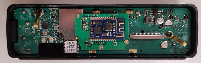
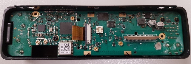
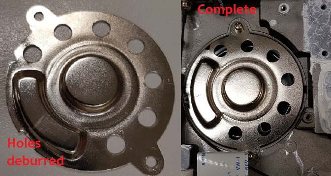
Note the little cut out area and two mini coax connectors on the left bottom of the picture. One of the mini connectors is for the coax tail that goes to the GPS external antenna SMA connector on the back of the radio. The other connector is unused. Obviously this is a provision to have a tiny built in GPS antenna to the display unit itself, but AnyTone have decided against doing this in the end. A tiny 15x15x6mm or 18x18x7mm active GPS antenna with a short coax tail terminating in a U.FL / IPX connector looks to be ideal if you want to try adding your own, see adding your own internal GPS antenna
The back side of the display board. Bluetooth removed.
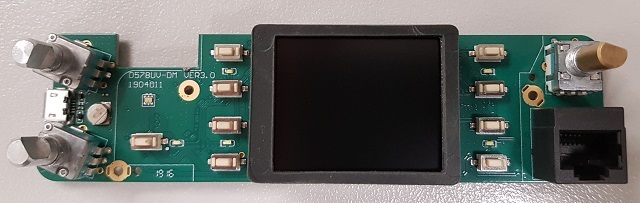
The front side of the display board.
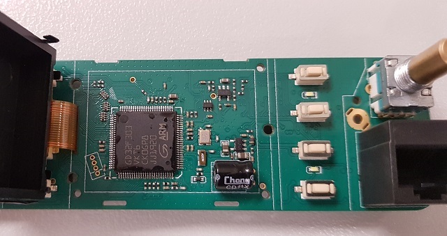
578 MCU hides under the LCD display:
The 578 main board top side:
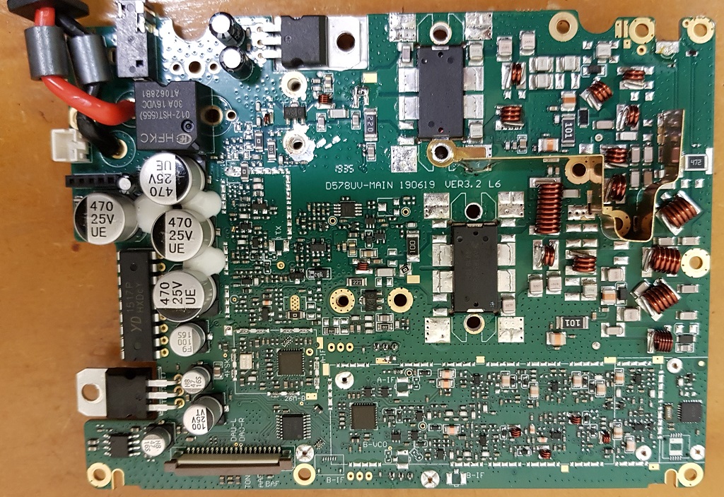
The 578 main board under side:
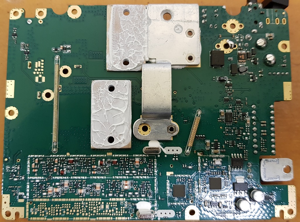
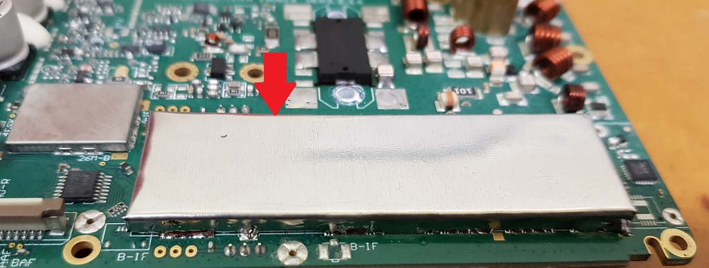
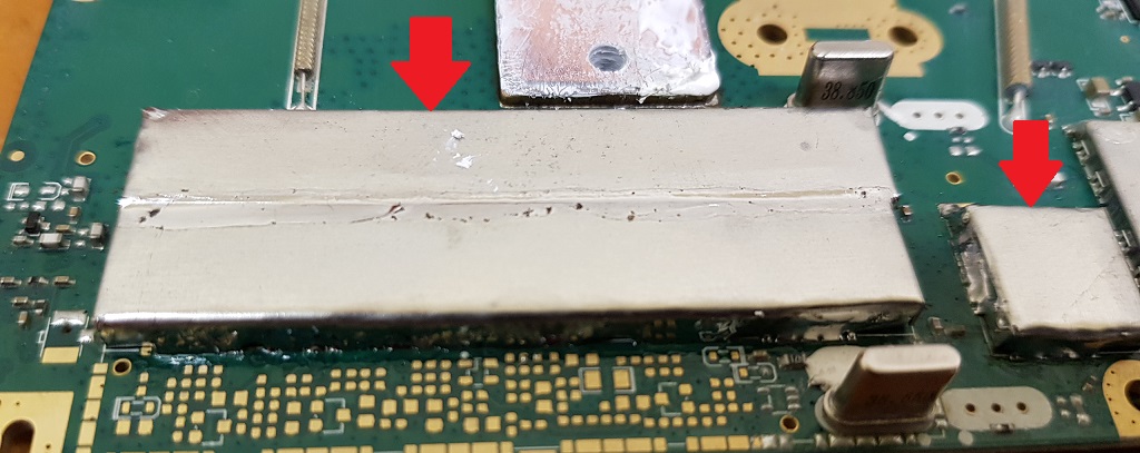
Close up of the twin 38 MHz IF crystal filters. Note the unpopulated PCB lands for a future version of the 578 that will have air band RX.
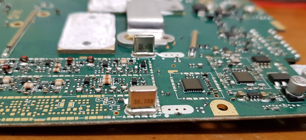
Notice how there is an unused position for a second crystal filter to be cascaded with the first... if you wanted even better selectivity, you could source a second pair of 38.550 and 38.850 MHz IF crystal filters, and install them after removing the little SMD 0 ohm resistor. But the 578 already has very good selectivity as it is already, so this is not really necessary.
What are the tiny backup batteries for?
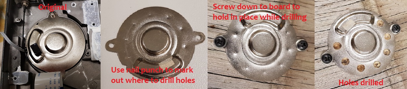
Modifying the internal speaker for extra volume Advanced (extensive disassembly)
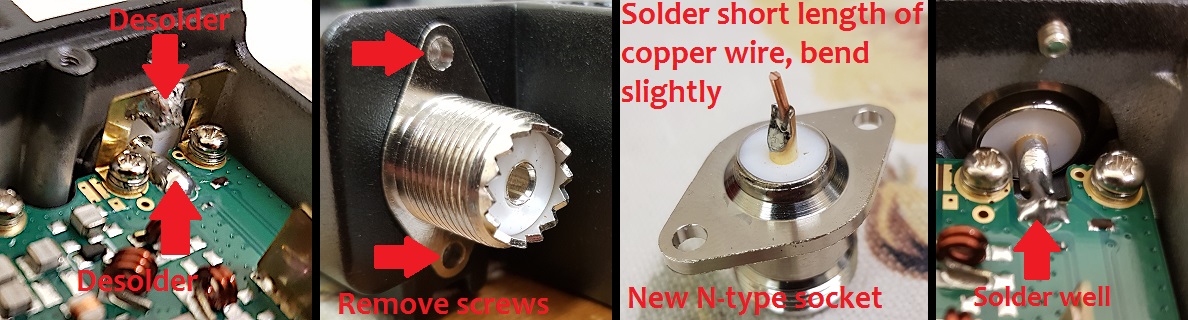
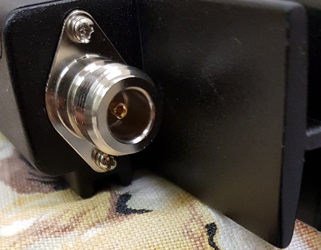
Replacing the SO-239 socket with an N-type socket Moderate
- Higher quality, better design connector, less ’junk’ connectors around in the N-type
- Slightly lower loss, especially at UHF
- Better VSWR / return loss; SO-239 connectors have an impedance ’bump’
- Better weatherproofing than SO-239 / PL-259 types
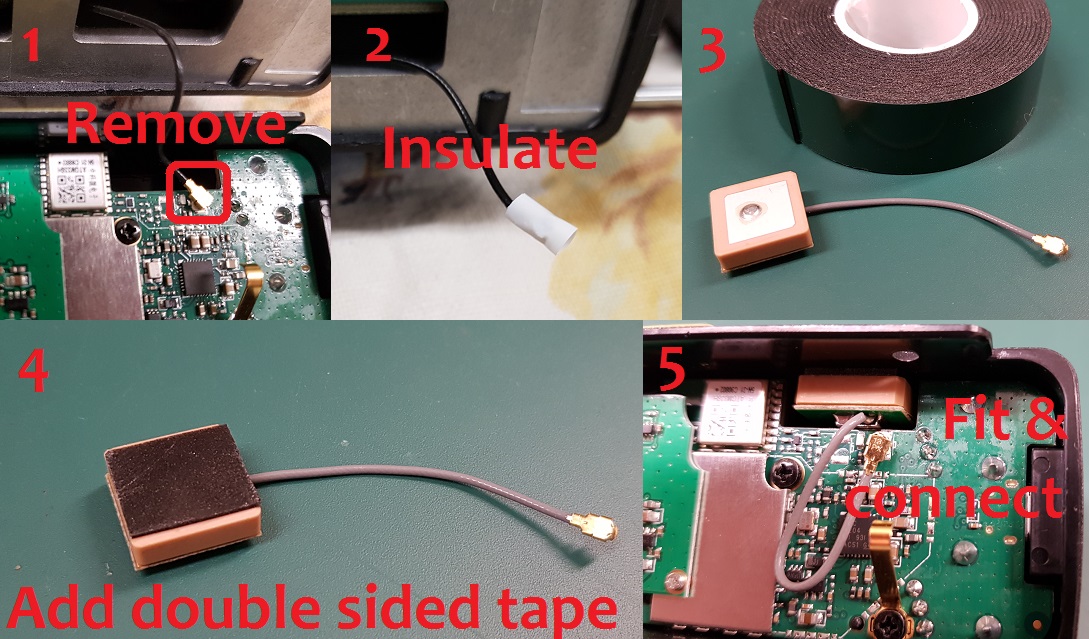
Adding an internal GPS antenna to the 578 Moderate
- Unclip the existing u.FL connector that goes to the rear mounted SMA socket
- Insulate the original u.FL connector and tuck it away somewhere; a little bit of 2mm or 3mm heatshrink is a professional way to do this, but some electrical tape is OK too
- Find some double sided tape (maximum of 1mm thick). The double sided foam tape pictured here is used in the automotive industry to affix exterior trim to vehicle bodies etc. and works well
- Add a small square of double sided tape to the top of the GPS antenna
- Clip in the new antenna connector - due to it’s tiny size, this can be a bit tricky to get mated correctly, be patient and don’t force it. Mount the new antenna in the cut out as shown below
Improved cooling for the 578 Moderate
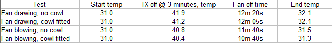
A good example of a small cowl added can be found here: http://f1dmg.free.fr/578a
However, if you are often going to be using high power, it would be a much better idea to fashion a bracket to hold a 120mm computer fan to the top of the heatsink. Noctua make some excellent quality, very acoustically quiet fans that would be excellent for this job.
Improved receiver shielding for the 578 Advanced
- GD32F303VKT6 ARM Cortex-M4 32 bit MCU with 3072kbyte internal flash and 96kbyte internal SRAM. 578s produced after mid 2022 will use an equivalent AT32 brand MCU.
- Toshiba TC58CVG1S3HRAIG 2Gbit / 256Mbyte NAND flash memory
- Sicomm CT3258TD baseband processor for DMR with built in AMBE2+ vocoder & 12.2 MHz oscillator
- Texas Instruments TLV320AIC3204 DSP / codec
- 4 x QA4818N transceiver ICs & 26.0 MHz reference oscillators. These devices have the same pinout as the more common AT1846S, but are more capable. One pair is being used as the 1st Local Oscillator for VFO-A and VFO-B, and the other pair are acting as a direct conversion 1st IF baseband receiver.
- RDA 5802N FM broadcast band receiver
- YD1517P (LM1517P equivalent) 2x 6 watt audio power amp, working in push-pull mode to give 12 watt output
- Two NXP AFT05MP075N LDMOS 70 watt RF power amps, 18dB narrowband gain, one each for independent VHF & UHF power amp stages
- VHF and UHF receive front ends each have four stages of varactor track tuned filtering
- ATGM336H GPS & BDS (BeiDou) positioning module (GPS models only)
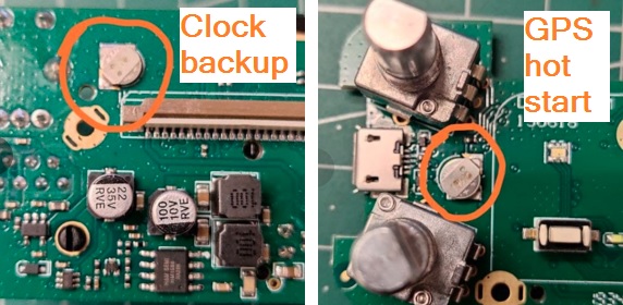
- Battery backup for real time clock, plus a second backup battery for GPS ’hot start’
Flash memory structure in the 578
- Reading the flash is perfectly safe, it is the writing of data that you need to be careful with.
- Through careless use when writing data, this software can most definitely ’brick’ or disable your radio, or cause hardware damage by writing RF output power values to destructively high levels for example. You accept all risk in use of the software.
- The radio will attempt to prevent overwriting of critical data in certain areas of the flash memory, typically stored between addresses 02F00000 and 02FDFFFF. It is generally better to create a set of CDD, CDI and SPI files to write to this area of memory, and write using icon update mode to ensure the radio MCU is safely halted.
- If using Flash Utility to write to the flash memory you need to apply a (hex) 20000 byte offset. For example, if you want to write to address 00000000 you should instruct Flash Utility to begin writing at 00020000. It is unknown why this is necessary, and exactly at what memory address this offset is no longer needed, but it applies at least as high as address (hex) 04000000.
- You should write to the radio in multiples of 256kbytes, even if you only want to change just one byte. (Do not forget the 128k offset that needs to be applied) This restriction doesn’t exist when only reading the flash.
- Download from this webpage here
- Download via Mega
- Download via Google Drive
- Download via Sabercat host
Flash Utility is compatible with the 578 of all flavours, 868, 878 & 878-II, Btech 6X2, Alinco DJ-MD5 & DJ-MD5X and Alinco DR-MD500/MD520. When reading from the radio, it might be a bit confusing to users to have to specify a file before reading begins - this is the file you will be saving your read results to.
Backing up or restoring vital alignment & configuration data of your 578
- Download Flash Utility software (10kb) from:
Download from this webpage here
Download via Mega
Download via Google Drive
Download via Sabercat host - Plug in your programming cable to the radio and your computers USB port, and power on the radio
- Start AT_Flash_Utility_v3.exe
- In the Start Address (Hex) box type 2F00000 [ 2F and five zeros ] and in the Length (Hex) box type E0000 [ E and four zeros ]. Take care to correctly enter the hex addresses given in this step.
- Click the Select File button, and navigate to the directory you wish to save the data backup file into. Enter a file name of "myvital.bin" then select Save. If you have more than one radio, or perhaps you own another model of radio (eg: 878 etc), make sure you save each backup to a different directory and clearly identify which individual radio that directory and it’s backup file belongs to.
- Select your usual Com Port, and then click the Read button. AT Flash Utility will then read the vital bits of flash memory and save it to a file called myvital.bin and takes about a minute to complete.
- After the read is complete, click on the OK button. Confirm that your myvital.bin file was saved to your directory and that its size is 896kb. If not, go back to step 4 again, making absolutely sure you have given the correct Hex address and length values.
- Close down AT Flash Utility.
- Rename the file myvital.bin to myvital.CDD (i.e. change the file extension from .bin to .CDD) This step is very important, do not skip this step!
- Restoring a saved backup file
This step shouldn’t be carried out unless you have strong reason to believe your RF alignment data is corrupt. There is inherent risk, though very slight, that writing data to parts of flash memory that isn’t normally user accessible can make things worse. Follow these steps carefully, and take your time.- It is assumed you already have downloaded Flash Utility as per Making a backup step 1 just above.
- Download some supporting files (<1 kb) necessary to restoring a backup from:
Download from this webpage here
Download via Mega
Download via Google Drive
Download via Sabercat host - Unzip these support files to your directory holding the backup file. You should now have the following files in there: myvital.CDD (your previously saved & renamed myvital.bin), myvital.CDI & myvital.spi
- Plug in your programming cable to the radio and your computers USB port, and power on the radio while holding down the P1 button & dial knob. Confirm the display shows "UPDATE MODE" with a flashing green LED
- In the CPS programming software, go to menu Tool > Firmware Upgrade (or manually execute QX_Firmware_Update.exe)
- Click on the Open Update File button, navigate to the directory where you saved your backup, select the myvital.spi file and click Open. Click on OK below the File Open Succesed! message. (If you have multiple radios and multiple backup files, make absolutely sure you have selected the correct backup file to send to the connected radio)
- Ensure Duplex box is ticked, and that Com Speed is set to 921600. Click on Write. This step will restore vital RF tuning data that is unique to your radio back in flash memory, and takes 25 seconds to complete.
- Turn the radio off, then power on the radio normally this time, without holding any buttons.
- You may need to set the time & date. The radio might also power up in Chinese language mode, this is OK, after writing your codeplug to the radio that will be corrected. You may need to power up the radio in test mode to change the band (MODE) or set the band with AT Options software to match the band you were using before, if you get Band Error when sending your codeplug back to the radio.
- You are now done!
Fix a frozen during boot up AnyTone 578 or Alinco DR-MD500 / DR-MD520 Easy
- Turn the radio off, leave it off for ten seconds, and turn back on
- Turn the radio off, remove all power to the radio for 5 minutes, then reconnect and power on
- Attempt a reset: turn the radio off, and then hold P2 and the dial knob in while turning the radio on
- Reflash firmware: turn the radio off, then hold the MENU and EXIT buttons down together just after power off, the LED will flash red and you can then use the CPS software to load your firmware file using Tool > Firmware Upgrade
- Reflash the SCT3258 baseband: Download the SCT3258 software, instructions and baseband files (3.18 Mb) from:
Download via Mega
Download via Google Drive Note Google has recently tightened security for downloads and this file may or may not be available to download by you entirely at Google's discretion
Download via Sabercat host
To enter the SCT update mode, hold down the dial knob and MENU keys while turning the radio on. From there, follow the instructions included in the download to write the latest baseband file V2.01.07BF to the SCT3258.
Once you have managed to regain control of the radio, the first thing to do is re-build your ’codeplug’ to remove any hidden corruption that caused the freeze in the first place. 99.9% of problems encountered are usually the result of poor ’codeplug’ practices. Using other people’s codeplugs, originating from several CPS versions back, and then added to piecemeal, is almost certain to cause problems. The solution to this is to ensure your codeplug is rebuilt which ensures the underlying data that your codeplug is built upon is fresh and consistent with the CPS and firmware version in use. Do not take any shortcuts in the following process!
- In CPS, load your old saved codeplug and export everything (Tool > Export > Export All)
- Go through all your Optional Setting and write them down or take screen shots of all the settings there. If you are using encryption, also record all your encryption keys. These settings and encryption keys are not saved by the Export All process.
- RESET the radio - this step is very important! If you do not do this, the old & possibly problematic data in the radio is not removed.
- In CPS, read from the freshly reset radio (yes, you are reading a ’blank’ radio, that is OK)
- Import everything saved from step 1
- Finish off your codeplug by attending to the Optional Setting & encryption keys if applicable and confirm all is correct
- Send the freshly rebuilt codeplug to the radio
- If you had a custom start up picture or background pictures, send those to the radio now
- Finally, save the rebuilt codeplug and ensure you use this saved file as the basis for any further changes you may make, and make sure you delete your old problematic codeplug file.
If these steps have not worked, there is a procedure that may help un-freeze your radio and get you going again. Note that this defroster will only work if the freezing is caused by memory corruption. If the problem is a hardware failure, then this will not work.
Quick defroster
Credit to Francesco IK8JHL & Andres CD2KDT and thanks to Jason Alexander for assistance with the Alinco models
This process is quick and simple, forcing the radio to undergo a reset. You will loose your codeplug, so make sure you have a saved copy first.
Download the AnyTone 578 fast defroster (1 kb):
- Download from this webpage here
- Download via Mega
- Download via Google Drive
- Download via Sabercat host
Download the Alinco DR-MD500 fast defroster (1 kb):
- Download from this webpage here
- Download via Mega
- Download via Google Drive
- Download via Sabercat host
Download the Alinco DR-MD520 fast defroster (1 kb):
- Download from this webpage here
- Download via Mega
- Download via Google Drive
- Download via Sabercat host
- Unzip the contents of the fast defroster for your model radio
- Confirm that your frozen radio can power up in the Icon Update mode: turn the radio off, hold the P1 and dial knob down while powering on the radio. You should see a screen with "UPDATE MODE" displayed. If you do not see this screen, this process will not work for you and the radio will have to go back to the supplier for repair or replacement.
- Start up the CPS, preferably using the latest version you can get. Go to menu Set > Set Com. Select the Com Port you normally use to program your radio.
- In the CPS, go to menu Tool > Firmware Upgrade. Click on the Open Update File button, navigate to the directory where you have unzipped the files and select the 578-Fast-defrost.spi file and click Open. Click on OK below the File Open Succesed! message.
- Ensure Duplex box is ticked, and that Com Speed is set to 921600. Click on Write. The data only takes a fraction of a second to be written to the radio.
- Turn off the radio, wait ten seconds, then turn it back on again. The radio should immediately go through a reset.
- You may need to set the time & date. The radio might also power up in Chinese language mode, this is OK, after writing your codeplug to the radio that will be corrected. You may need to power up the radio in test mode to change the band (MODE) or set the band with AT Options software to match the band you were using before, if you get Band Error when sending your codeplug back to the radio.
- You are now done!
Download the Alinco DR-MD500 full defroster pack (2.3 Mb) (Note: not suitable for DR-MD520) from:
(There is no full defrost pack for the DR-MD520 as yet)
- Unzip the contents into a new directory
- Plug in your programming cable to the radio and your computers USB port, hold down dial knob & P1 while powering on the radio, and confirm the display shows "UPDATE MODE"
- Start AT_Flash_Utility_v3.exe In the Start Address (Hex) box type 2F00000 [ 2F and five zeros ] and in the Length (Hex) box type E0000 [ E and four zeros ]. Then click the Select File button, and navigate to the directory you have unzipped the defrosting files into. Enter a file name of "myvital.bin" then select Save.
- Select your usual Com Port, and then click the Read button. You will get two error messages, this is fine, just click on OK. AT Flash Utility will then read some vital flash memory and save it to a file called myvital.bin and takes about 55 seconds to complete.
- After the read is complete, click on the OK button. Confirm that your myvital.bin file is in the working directory and that its size is 896kb. If not, go back to step 6 again, making absolutely sure you have given the correct Hex address and length values.
- Close down AT Flash Utility.
- Rename the file myvital.bin to myvital.CDD (i.e. change the file extension from .bin to .CDD) This step is very important, do not skip this step
- Turn off your radio, and again hold down the dial knob & P1 while powering on the radio, and confirm the display shows "UPDATE MODE"
- Start up the CPS, preferably using the most current version CPS available for your model. Go to menu Set > Set Com. Select the Com Port you normally use to program your radio.
- In the CPS, go to menu Tool > Firmware Upgrade. Click on the Open Update File button, navigate to the working directory and select the flash fresh reset .spi file and click Open. Click on OK below the File Open Succesed! message.
- Ensure Duplex box is ticked, and that Com Speed is set to 921600. Click on Write. This step will wipe your flash memory clean, and takes quite some time (an hour or more) to complete.
- Turn off your radio, and again hold down the dial knob & P1 while powering on the radio, and confirm the display shows "UPDATE MODE"
- In the CPS, go to menu Tool > Firmware Upgrade. Click on the Open Update File button, navigate to the working directory and select the icon .spi file and click Open. Click on OK below the File Open Succesed! message.
- Ensure Duplex box is ticked, and that Com Speed is set to 921600. Click on Write. This step will rebuild icons and text bitmaps in flash memory, and takes a minute or two to complete.
- Turn off your radio, and yet again hold down the dial knob & P1 while powering on the radio, and confirm the display shows "UPDATE MODE"
- In the CPS, go to menu Tool > Firmware Upgrade. Click on the Open Update File button, navigate to the working directory and select the myvital.spi file and click Open. Click on OK below the File Open Succesed! message.
- Ensure Duplex box is ticked, and that Com Speed is set to 921600. Click on Write. This step will restore vital RF tuning data that is unique to your radio back in flash memory, and takes 25 seconds to complete. This is another very important step that you should not skip, otherwise your radio will not properly transmit on DMR.
- Power cycle the radio normally this time, without holding any buttons. It should boot up somewhat normally this time. You may need to set the time & date. The radio might also power up in Chinese language mode, this is OK, after writing your codeplug to the radio that will be corrected. You may need to power up the radio in test mode to change the band (MODE) or set the band with AT Options software to match the band you were using before, if you get Band Error when sending your codeplug back to the radio.
- You are now done!
I recommend updating to the latest firmware version available for your model after doing this process, if you have not already done so. You MUST reset the radio by holding down the dial knob and P2 while powering on the radio after doing a firmware update, this is extremely important.
If these suggestions still do not un-freeze your radio then, sadly, it it likely the problem is a hardware fault, and no amount of resets, reloading of firmware or codeplugs, or performing any special procedure will fix that. You should get in touch with the seller of the radio to discuss repair.
Preventing your 578 or MD500 / MD520 from freezing or locking up and how to cure many problems
- First make sure your CPS software version matches the firmware version presently in your radio
- In CPS, load your existing configuration codeplug and export everything (Tool > Export > Export All)
- Go through all your Optional Setting and write them down or take screen shots of all the settings there. If you are using encryption, also record all your encryption keys. These settings and encryption keys are not saved by the Export All process.
- RESET the radio - this step is very important! If you do not do this, the old & possibly problematic data in the radio is not removed.
- In CPS, read from the freshly reset radio (yes, you are reading a ’blank’ radio, that is OK)
- Import everything saved from step 1
- Finish off your codeplug by attending to the Optional Setting & encryption keys if applicable and confirm all is correct
- Send the freshly rebuilt codeplug to the radio
- If you had a custom start up picture or background pictures, send those to the radio now
- Save the rebuilt codeplug and ensure you use this saved file as the basis for any further changes you may make, and make sure you delete your old problematic codeplug file.
- Ensure you rebuild your codeplug using these steps EVERY time a firmware update is made.
Writing your own .CDD files Advanced
- You must ensure your CDD file is 256kbyte or some multiple of that size
- You must ensure that your data to be written starts at a 256kbyte page eg: hex addresses 00040000, 00080000, 000C0000, 00100000, 00140000 etc.
- And then lastly, you will write this data with an offset of (hex) 20000 bytes above the intended actual location you wish to write to.
Updating the SCT3258 baseband / DMR codec firmware
- Download via Mega
- Download via Google Drive Note Google has recently tightened security for downloads and this file may or may not be available to download by you entirely at Google's discretion
- Download via Sabercat host
- Exploiting the capabilities of the TLV320AIC3204 audio codec chip. This is a very powerful chip with the possible scope to facilitate DSP noise reduction, equalisation, tone control and digital AGC audio.
- Explore some new fonts, perhaps some screen colour changes and icon customisation
- Investigate if the display unit could be remote mounted by use of a longer 40 pin ribbon cable and a custom 3D printed backing plate for physically mounting the head
- Patching the vocoder in the SCT3258 for something else entirely. There is a very strong resemblance between AnyTone’s SCT3258TD_UpdateFlash_v2_01_05NJ.hex and Hytera’s PD36x series SCT3928_UpdateFlash_V2_01_05PD.hex - both in name and hex content. The Hytera can already load different hex files for AMBE, SELP, NVOC & COMM vocoders, but this is slightly dependant on the different hardware installed in the Hytera radios. It would be very interesting to experiment with an open source ham vocoder like FreeDV’s Codec2, and see if this could be used to replace the AMBE2+ vocoder in the SCT3258. Sadly the SiComm hex code that gets sent to the SCT3258 is encrypted, so for the moment any patching is unlikely
© Copyright Jason Reilly, 2018-2022
A huge thank you to Jason Reilly (VK7ZJA) who passed away on 01/17/2023
He allowed me to create this "mirror pages" of his collection of
mods and information.
The original Page was located at
http://members.optuszoo.com.au/jason.reilly1/868mods.htm