A huge thank you to Jason Reilly (VK7ZJA) who passed away on 01/17/2023
He allowed me to create this "mirror pages" of his collection of
mods and information.
The original Page was located at
http://members.optuszoo.com.au/jason.reilly1/868mods.htm
Modifications, hints, tips and technical information for the
AnyTone AT-D878UV
AnyTone AT-D878UV-II
AnyTone AT-D868UV
and
BTech DMR-6X2
(Some relevance to Alinco DJ-MD5 & Radioddity GD-AT10G too)
dual band DMR digital handheld radio
Version 20 --- 20 October 2022
Updates made since the previous version are shown in this purple colour
This information is primarily intended for amateur ’ham’ radio operators who wish to maintain and adjust their AT-D878UV, AT-D878UV-II, AT-D868UV or DMR-6X2. Any regulatory authority approval (e.g. FCC certification) may become invalid by the use of this information. Users should always ensure that they and their radios are operating in accordance with their licence conditions. Many of these mods may also invalidate any manufacturer warranty you may have. In any case, the user alone accepts all responsibility and risk from the use of this information and tools provided here.
General warnings to all users:
- Codeplug version, CPS programming software version and firmware version present in the radio must all match in version number. If not, very strange things happen. You must REBUILD your codeplug every time a new CPS or firmware version is installed. This keeps the underlying data sent to the radio consistent in version.
- For the same reason above, I would caution anyone from sharing and using other people’s codeplugs. While it might be convenient, you can’t be guaranteed what version the shared codeplug was built under, and therefore whether it would work properly under the firmware version installed in your radio. You just can’t tell, the CPS won’t tell you unless it is a very early version codeplug. Save yourself a lot of headaches and REBUILD the codeplug before writing it to your radio.
- Be very careful not to accidentally hit the PTT (Push to Talk) button while you have the USB cable plugged in to the radio, or while it is sitting in the charger. Doing so can cause RF to be picked up by the USB cable or charger, and cause damage to the hardware - both radio and charger. This has happened to some unfortunate 878 owners previously.
- Don't have the USB cable inserted when you have any channel that may autonomously transmit, such as APRS, roaming or lone worker feature is active (credit to Jerry Kuhn)
- Keep the radio 1 foot away from your cellular / mobile phone, cordless phone and Wi-Fi devices at ALL times.
- Use caution if writing non standard data to the radio in some of the advanced modifications listed below. It is possible to cause the radio to cease functioning correctly if instructions are not carried out with care.
Page Index
- Introduction
- Band Error and five ways you can fix it
- Help! I can’t change zones any more!
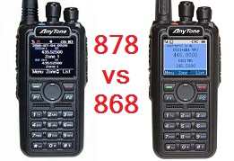
- Are the AnyTone AT-D878UV and Btech DMR-6X2 really the same radio?
- What are the differences between the AnyTone AT-D868UV, AT-D878UV and AT-D878UV-II?
- So can you upgrade an AT-D868UV or Btech DMR-6X2 to an AT-D878UV?
- Can you upgrade an 878 to an 878-II?
- Similarities between Alinco DJ-MD5, Radioddity GD-AT10G and AnyTone 878?
- Comparison of the AnyTone 868, 878, Btech 6X2 and Alinco DJ-MD5
- Hint when using the programming software / CPS
- Virus detected! Is the CPS software really safe to use?
- Hints & tips for upgrading firmware
- Trouble getting the drivers to install or work properly on Win 7 or 10
- Strange error messages and what you can do to fix them --- Band Error has it’s own section, click here
- A website with lots of great hints & tips for the AnyTone DMR radio family
- Looking for a guide on how to setup APRS? This website shows you how
- Hint for being able to recall and dial Private Call IDs
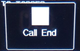
- How to reply on an active channel found while scanning
- Hint when using the radio menus
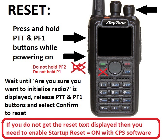
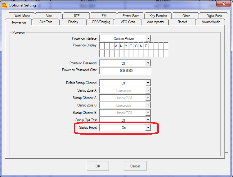
- How do I reset the radio? -or- Why won’t the radio reset?
- Compatibility of encryption
- Cross compatibility of accessories Updated: more compatible programming cables discovered
- Need a spare battery for your AnyTone AT-D868UV, AT-D878UV or BTech DMR-6X2?
- Battery meter & how it relates to actual battery life remaining
- Tips for extending the life of your battery
- Differences in battery sizes
- Custom engraved call sign labels for your radio.
- A DIY 3D printed custom desk stand
- Custom background display files
- Guide to the icons & what they mean (updated)
- Alternate GPS icons to download (878 only)
- Hint when using 'enhanced microphone audio’
- Make your radio sound like a Motorola and other fun tone sequences to play with (updated)
- Using the address book to dial EchoLink nodes
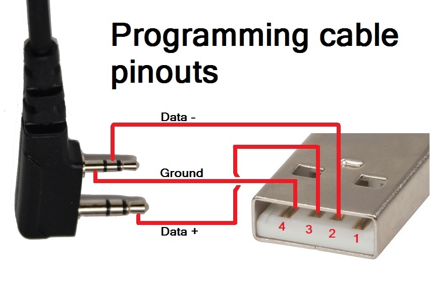
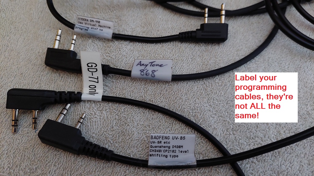
- 868 / 878 / 6X2 programming cable pin out Updated: label your programming cable!
- Known button held during power up sequences
- Selecting operational bands
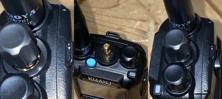
- New knobs for the 878
- Antennae for the 868 / 878 / 6X2
- Screen scratch protection
- Protective carry case options for 868 / 878 / 6X2
- Using a car drink holder for the 868 / 878 / 6X2
- DIY Headphone adaptor
- Hint when using a Bluetooth earpiece
- How to control playback of recordings using PC software
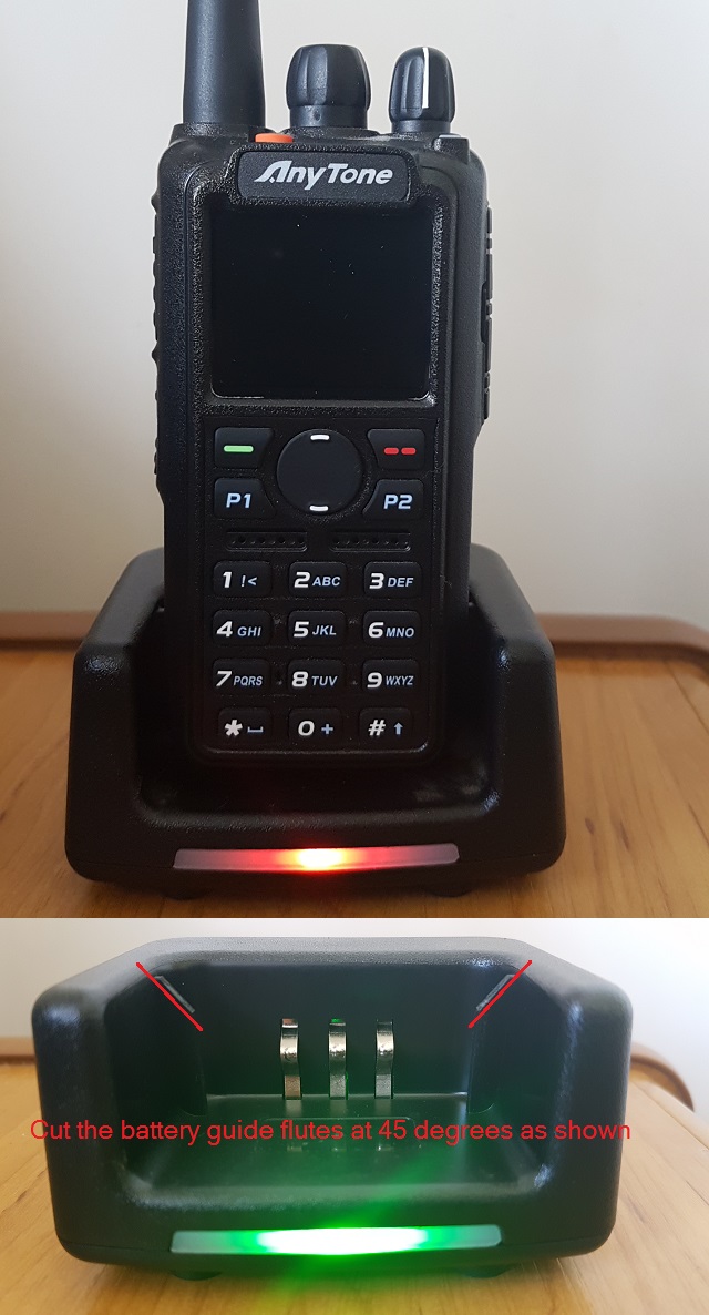
- Modifying the Radioddity GD-77 or TYT MD-390 or Retevis RT3 charger for the 878
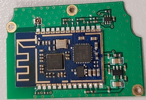
- How to disassemble the radio / fitting the new Bluetooth module
- Improving top mounted LED visibility
- Expanding RX frequencies New: modified AnyTone 878 firmware version 1.27, modified 878-II firmware version 2.05, modified 868 firmware version 2.40, modified Alinco DJ-MD5 firmware version 1.13e and Alinco DJ-MD5X firmware version 1.11 now available to download
- AnyTone 868 or 878 or Btech 6X2 on VHF air band?
- What about 220 MHz, could the 868 / 878 be used on the 1.25 metre band?
- Sensitivity plots
- I heard VHF was deaf on the 878. Is that true?
- Can the 878 be used as a scanner?
- My receive keeps cutting in and out on FM, can that be fixed? (updated)
- Introduction to hex editing
- Theory behind the frequency expansion mod
- Expanding FM band frequencies 76 to 121 MHz
- Changing the display font / modifying some of the icons
- Modify a speaker microphone to keep out DMR pulsed RF feedback
- Swapping Btech DMR-6X2 firmware into an AnyTone AT-D878UV
- Obtaining faster GPS lock for the 868
- Much faster GPS lock for the 878, 868 & 6X2
- Enabling full test / self adjustment mode
- AnyTone Options software download New: AT Options version 8 now available, supporting 868, 878, 878-II, 578 of all flavours and Alinco DJ-MD5, DJ-MD5X, DR-MD500 & DR-MD520
- Resetting your power on password (updated)
- Programming password lock
- Resolving received noise / perceived poor VHF sensitivity issues (improved shielding)
- FCC Part 90 approval information
- A look inside the 878
- Repairing a faulty charger base
- Bugs on the 868 & 878
- Hardware faults with the 868 / 878 / 6X2
- General technical information
- Flash memory structure in the 868 / 6X2 / 878
- Flash Utility software
- Backing up or restoring vital alignment & configuration data of your radio
- Writing your own .CDD files
- Fix a frozen or stuck during boot up 868 / 878 / 6X2 / DJ-MD5 / DJ-MD5X
- Preventing your radio from freezing or locking up & also cures many problems
- French text help file for 878 (updated for v1.26)
- Updating the SCT3258 baseband / DMR codec firmware Updated: includes latest version V2.01.07BF
- Future developments & ideas
AnyTone’s AT-D868UV, AT-D878UV & AT-D878UV-II and its twin Btech DMR-6X2 (unless otherwise stated, I’ll refer to them going forward as simply ’ 878 ’) are excellent dual band DMR / FM handheld radios. They have a fabulous receiver, enough memory to hold the entire DMR user database - for the time being, anyway! - and have many nice features, allowing the user to control just about every aspect of the radio from its operating controls.
Presented here is a collection of modifications for the 878. Not all of these modifications are my own ideas, and credit has been given to the original author of the information as best as I have been able to find. Each modification is rated on a difficulty scale as follows:
Easy: no specialist skills required, easy soldering, minimal disassembly. If the thought of picking up a screwdriver makes you break out in a cold sweat, however, you might want to seek some assistance
Moderate: some skill required in soldering, electronics and/or computing, some disassembly needed. Any self respecting ham / electronics geek will be comfortable at this level.
Advanced: excellent soldering skills required, very good knowledge of electronics and/or computing, extensive disassembly.
If you have any more information or modifications that you'd like to share here, please contact me at vk7zja at gmail dot com and I will make sure you receive credit for your work, though you are welcome to remain anonymous if you wish.
17/01/2023 It is with heartfelt sadness that I inform you all that Jason passed away peacefully this morning.
If you have any more information or modifications that you'd like to share here, please contact me at jason at db1ig dot de and i will make sure you recieve credit for your work, though you are welcome to remain anonymous if you wish.
-
- Ensure that you do not have any power on password active. If you do, you must use the CPS software to remove it first.
- Download Colin G4EML AT Options version 8 (17kb) software from:
Download from this webpage here
Download via Mega
Download via Google Drive
Download via Sabercat host - Determine what band the codeplug is. Without the radio connected to the computer, open the codeplug .rdt file into the CPS software, and use menu Model then Model Information to display information about the codeplug. In the middle of the window will be 'Frequencys’ and next to that will be Mode with a number. This is your band number, write it down. Click on Cancel for now.
- Connect your radio to the computer with the programming cable now, and open AT Options software. Select your usual Com port and click Read.
- Next to Frequency, use the pull down list to select the band that matches the Mode number you wrote down earlier in step 2
- Click Write to change the radio band
- Back in the CPS programming software, you should now be able to write the codeplug .rdt file to the radio without a Band Error
Note- there is a bug in the CPS programming software: Local Information will not show the correct frequency band the radio is set to, but Model > Model Information does show the correct frequency band
Method 2: changing the band of your codeplug file to match the current band setting in your radio (also very easy)
- Download & unzip Francesco IK8JHL automated script tool (18kb) from:
Download from this webpage here
Download via Mega
Download via Google Drive
Download via Sabercat host - Make a backup copy of your codeplug .rdt file and keep it somewhere safe. This script tool will alter your codeplug file ’live’ without making any backup
- Determine what band your radio is set to: Open CPS programming software, and use menu Set > Set Initialization to clear memory contents first, then select Program > Read From Radio. You can select just ’Other Data’ to read. Let the CPS programming software read the radio contents, and once done select menu Model > Model Information. In the middle of the window will be 'Frequencys’ and next to that will be Mode with a number. This is your band number, write it down. Click on Cancel for now.
- Copy your codeplug .rdt file into the working directory for the RDT Band Conversion script tool
- Start up the script tool by executing the Convert.bat file
- Tell the script tool the name of your .rdt codeplug file, and the band number (given in HEX - the on screen menu will guide you) that you wish to convert your codeplug over to
- The tool will automatically edit your codeplug .rdt file to your desired band, and rename it to confirm the changes were made. Copy your converted codeplug .rdt file back into your regular folder where the CPS software looks for & loads it’s codeplug files
- Back in the CPS programming software, load the converted .rdt codeplug file and you should now be able to write the codeplug .rdt file to the radio without a Band Error
Note - there is a bug in the CPS programming software: Local Information will not show the correct frequency band the radio is set to, but Model > Model Information does show the correct frequency band
Note 2 - because of the batch file / script nature of this tool, expect your anti-virus software to complain about it, but it is 100% safe to use.
Method 3: changing the band of the codeplug to match the radio (requires hex editing skills)
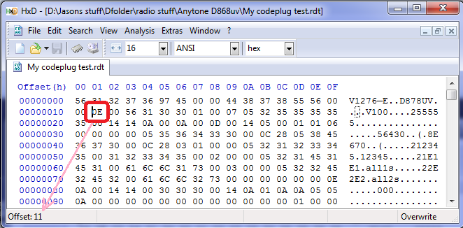
The red circle indicates byte 0x0011, which determines what band the codeplug is, change that data to 0E for band 14, or change it to 12 for band 18. Also note how the offset (address) shown in HxD indicates where your cursor is placed.
- Determine what band the radio is set to. Connect the radio to the computer with the programming cable and with the CPS programming software, read from the radio.
- In the CPS programming software use menu Model then Model Information to display information about what was read from the radio. In the middle of the window will be 'Frequencys’ and next to that will be Mode with a number. This is your band number, write it down. Click on Cancel for now and close down the CPS programming software.
- Convert the band number you wrote down into hexadecimal. As an example, if it is Mode 00015, 15=0F in hexadecimal. Write that down too.
- Now open your codeplug .rdt file in a hex editor, and look at the byte at address (hex) 0x0011. This is the byte that tells the CPS software what 'band’ the codeplug is. Change the value of the byte at address 0x0011 to the hex number you just calculated in step 3. Save the edited .rdt file under a new name.
- Start up the CPS programming software, load the edited .rdt file that you saved with a new name and send it to the radio.
- Frank, KB2MXV, has made a nice YouTube video on the process of hex-editing your band byte. He’s using a different hex editor, so it will look a little different to the above picture, but the general process is the same. Take a look at: https://youtu.be/atMWu00_33U
Method 4: when all else fails, use this export all / import all method (most reliable method, but needs the most work)
- In the CPS programming software, open your codeplug.
- Use the menu Tool then Export and look at the top of the window that opens - there is an Export All button. Click it.
- Give your export a name, and click Save. This will export all your frequencies, contacts, zones etc etc to .csv files. This could take a few minutes with no apparent progress or activity especially if your digital contact list is large, wait until an Export Complete! message is shown
- There are some settings that are not exported, such as Optional Setting information, APRS and Encryption (if you happen to be using them). Go through and write down, take screen shots or take photos of these.
- Now connect the radio to the computer with the programming cable and with the CPS programming software, read from the radio.
- Use the menu Tool then Import and look at the top of the window that opens - there is an Import From File List button. Click it.
- Find the file you saved / exported in step 3 above, and click Open. This will import all your frequencies, contacts, zones etc etc to .csv files. This step can also take a few minutes to finish, wait until the Import Complete! message is shown
- Go through the Optional Setting / APRS / Encryption settings and restore all your settings as they were before, referring to your notes, screenshots or photos from step 4 above
- Save your newly rebuilt codeplug with a new name, perhaps including the mode number in the file name for easy reference
- Now write the fully rebuilt codeplug to the radio
Method 5: change radio bands to match codeplug via radio Test Mode menus (if enabled)
- Turn off the radio, then while holding down P4 key & pushing in the dial knob, power up the radio. Keep holding them until you see ’TEST MODE’ on the screen, and release the keys. If this is not displayed, then this method will not work for you.
- After the radio has fully powered up, you should see MODE:000xx on the screen. If you don’t, use the up/down buttons until you do.
- Then rotate the dial knob to set a new MODE value to match the codeplug you are trying to send to the radio, and simply turn off the radio to set that value.
- After turning the radio back on normally, you should now be able to write your codeplug to the radio
Help! I can’t change zones any more!
So you’ve just updated your firmware version, and the up/down zone change button doesn’t seem to work any more. Must be a bug in the firmware, right? Wrong!!
If you read the firmware change log notes, you will find a new feature has been introduced: Zone Hide. Some people find it useful to hide an infrequently used zone until they need it, for example when travelling to another city.
By default, when you re-use your old codeplug file, CPS will hide all except your very first zone. You need to go through and unhide all your zones. Untick the following selection for all zones you want to be available:
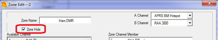
Of course, this wouldn’t have happened if you had followed the recommended best practice to not re-use your previous version’s saved codeplug.
Yes, it will work - sort of - but sooner or later you will run into a problem, and the reason is a subtle inconsistency in the data formatting used between different versions. This zone hide issue is one such ’issue’ - by default all the zones from your previous version codeplug are hidden. By rebuilding your codeplug, you avoid that. So, this ’problem’ isn’t a bug, it is failure to read notes and failure to follow recommendations / best practices.
Every time you upgrade firmware and use a new CPS version, you should REBUILD your codeplug to keep all the underlying data consistent with the new version of firmware & CPS being used.
- Early version 868: uses GD32F303VE MCU which has 512k of internal flash memory and 64k of SRAM. This uses the ’V1’ 868 firmware. You can see an example of this at Carlos’ Twitter: https://twitter.com/eb4fbz/status/880697136819691520?lang=en
- First ’V2’ revision 868: uses a GD32F303VE MCU with 512k of internal flash memory and 64k of SRAM. There were also some other hardware changes to the PCB making minor improvements all round. This uses the ’V2’ 868 firmware. You can see an example of this variant on the FCC Part 90 approval web portal at https://fccid.io/T4KD868UV/Internal-Photos/int-photos-3496060
- Second ’V2’ revision 868, and 878: identical to the first ’V2’ hardware except is now fitted with a GD32F303VG MCU with 1024k of internal flash memory and 96k of SRAM. This revision uses the ’V2’ 868 firmware, or of course 878 firmware in an AT-D878UV. You can see examples of this PCB right here at this page below.
- Despite these variations, you could likely apply many of these hints, tips & modifications across all three hardware revisions and 868 or 878 models.
The 878-II has further differences again: the flash memory chip has been upgraded from 1Gb to 2Gb, and has an all-new daughter board that handles Bluetooth and the FSK receiving function for analog FM APRS receive.
So can you upgrade an AT-D868UV or Btech DMR-6X2 to an AT-D878UV? Advanced
Yes, this is possible for the second ’V2’ revision hardware. One of the best guides on how to do this comes from F5UII Christian https://www.f5uii.net/en/convert-at-d868uv-to-at-d878uv-analog-aprs-roaming/
Also refer to:
https://github.com/geary/AnyTone-D868UV/issues/59 and
http://radioaficion.com/news/how-to-convert-an-at-d868uv-to-at-d878uv/ (Credit to Axelko)
- Change the WSON8 epad surface mount 1Gbit flash chip to a 2Gbit flash chip. The 878-II firmware checks for the presence of 2Gb of flash, and if it does not find it, will abort power up. Swapping this IC requires specialist equipment like SMD hot air reworking station and you need to be highly skilled in SMD reworking to safely achieve this swap without damaging the main board or other surrounding components
- Obtain the new combination FSK / Bluetooth daughter board and fit. There is a small wire to also solder from the daughter board to the main PCB as well
- And lastly, you’ll need to force the 878-II firmware into the 878. The QX-update software used for this purpose has checks to prevent the user from doing that, but they can by bypassed if you know what you are doing
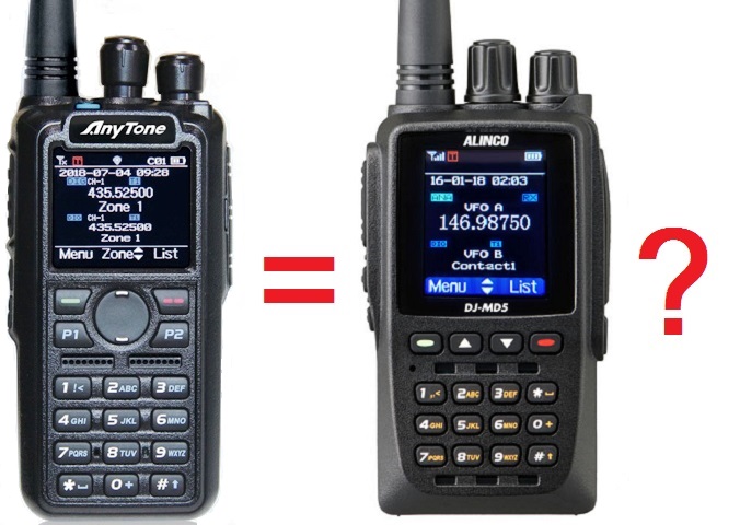
Similarities between Alinco DJ-MD5, Radioddity GD-AT10G and AnyTone 878?
A quick glance at Alinco’s new dual band DMR handheld DJ-MD5 shows many similarities to the AnyTone 878 radio: similar size, similar general layout, near identical display icons, display layout and menus, and the Alinco CPS programming software looks & feels the same as the AnyTone CPS. There are some differences, too: change in case and branding labels of course, more narrow and taller LCD display, no P1 or P2 function buttons, no top mounted PF3 button, and more.
Closer examination of the internals of the Alinco DJ-MD5 from the FCC approval portal reveals that the DJ-MD5 and 868/878 are different internally, but that both use the very same major components e.g. MCU, AT1846, RF PAs, DMR DSP, bulk flash memory chip and so on. It appears as if the DJ-MD5 is a redesigned AnyTone 878. To take it one step further, I even downloaded the CPS programming software for the Alinco, and it was able to talk to the AnyTone - it recognised that the model didn’t match, but that in itself proves that the Alinco & AnyTone share the same USB driver, same MCU and same USB communication protocols.
https://fccid.io/PH3DJ-MD5
You can get more information about the Alinco DJ-MD5 from:
- http://hvdnnotebook.blogspot.com/2018/11/review-alinco-md-5-series-dmr-radio.html
- http://hvdnnotebook.blogspot.com/2018/11/teardown-alinco-dj-md5tgp.html
- http://hvdnnotebook.blogspot.com/2019/03/frequency-expansion-alinco-dj-md5tgp.html
The Radioddity GD-AT10G is a UHF only version of the AnyTone 868 (despite the blue top button) with 200000 digital ID contacts available, 10 watts claimed RF output power on UHF, and a frequency range of 400-480 MHz. Modification to restore the VHF band is most definitely not possible, as all the VHF components - numbering in the hundreds - have been removed. However, apart from that, it is suspected that many of the modifications listed here will be applicable or at least adaptable to the Radioddity GD-AT10G. The FCC ID for the GD-AT10G is 2AN62-AT10G, but because it is the same hardware as the AnyTone 868 UHF only version, it once was listed under FCC ID T4KD868SUHF. You can see various technical information on the FCC website relating to Part 90 approvals by searching using these two model IDs.
Comparison of the AnyTone 868, 878, Btech 6X2 and Alinco DJ-MD5
Thanks to the wizard John Miklor, we have the following quick comparison chart of the AnyTone 868, 878, Btech 6X2 and Alinco DJ-MD5:
http://www.miklor.com/COM/Compare-DMR.php
- Under the original firmware, before you do any upgrades, export everything (Tool > Export > Export All)
- Go through all your Optional Setting and write them down or take screen shots of all the settings there. If you are using encryption, also record all your encryption keys. These settings and encryption keys are not saved by the Export All process.
- Power up the radio holding the PTT and top blue / orange button, and ensure the top LED is flashing red. Upload the new firmware using the CPS software menu Tool > Firmware and Icon Update
- RESET the radio - this step is very important! If you do not do this, the old data in the radio could conflict with the way the firmware expects the memory to be formatted after upgrading.
- If there is a baseband update with the new firmware release, do this now. Power up the radio holding the top orange / blue button and the # button until the message "This is Boot Mode for SCT!!!" is displayed. Use a freshly installed version of the SCT_PORT Host Controller software on your PC to send the new SCT3258 hex file to the radio. Older versions of the SCT_PORT Host Controller software may not be able to load all the required information, despite giving no error or other failure indication
- If there is an icon update with the new firmware release, do this now. Power up the radio holding the PTT and the lower side button until the message "UPDATE MODE" is displayed. Upload the new icon file using the CPS software menu Tool > Firmware and Icon Update
- Install new version CPS
- Go to Tools > Options and tick the GPS / Bluetooth / 500 Hours record / APRS options that apply to your radio.
- Now read from the freshly reset radio (yes, you are reading a 'blank’ radio, that is OK)
- Import everything saved from step 1
- Finish off your codeplug by attending to the Optional Setting & encryption keys if applicable and confirm all is correct
- Send the freshly rebuilt codeplug to the radio
- If you had a custom start up picture or background pictures, send those to the radio now
- Finally, save the codeplug and ensure you use this saved file as the basis for any further changes you may make
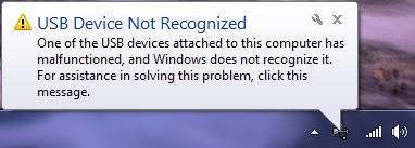
Trouble getting the drivers to install or work properly on Win 7 or 10
(Credit to Carsten Bauer VK6PCB, Chris Pyle & Duane Reese)
Some people have had problems with the drivers AnyTone / GigaDevice supplies to get the USB communicating with the radio when using Windows, especially Windows 10. Check these solutions to see if they can help you:
If you have troubles with what Windows installs by default, create a Windows restore point first (just to be safe) and then download and update to the latest GD32 drivers here: http://www.connectsystems.com/products/top/radios/DS878UV_SOFTWARE/GD_VirtualComDriver%20v2.0.2.4944.zip (921kb) then select the x64 folder for 64 bit Windows, or x86 for 32 bit Windows operating systems
- Win 7: when Windows starts, hold F8 to get into the 'advanced boot options’ and select 'Disable Driver Signature Enforcement: Loads installed software that has invalid or missing signatures.’
- Win 10: Press and hold the shift key on your keyboard and click the Restart button. Select Troubleshoot > Advanced options > Startup Settings and then click the Restart button. When your computer restarts, you’ll see a list of options, press F7 to select Disable driver signature enforcement. Once the computer restarts, go and install the AnyTone driver.
- Out of date or invalid usbser.sys system file in c:\windows\system32\drivers folder can also cause problems. Find a new version 6.1.7601.17xxx of usbser.sys, and manually copy it into your system32 drivers folder after booting into MS DOS mode, and restart the computer.
- Some computer’s USB controllers can have trouble detecting the USB connection to the 868 / 878 if the radio is connected via it’s programming cable while turned off, then turned on after the cable is connected. If you find you have this problem, try plugging in the USB cable into the PC while your radio is powered up. Normally that’s a big no-no, as you can induce spurious transitions on the USB data lines which can lead to strange things happening. In this case it can result in a successful connection! The working theory is that it is some PC USB controllers might be too impatient waiting for the radio’s USB to respond while it is busy booting up, but if it’s already powered up the radio MCU responds quick enough to keep finicky PC USB controllers happy.
| |
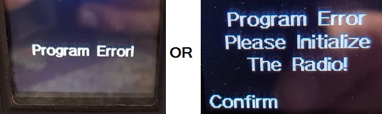
Band Error has it’s own section, click here to see five different methods on how to fix this problem. |
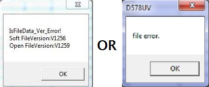 |
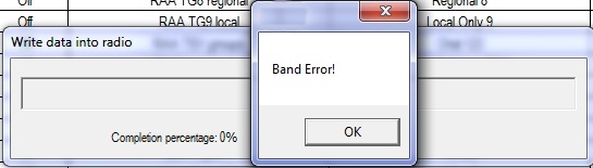
If you see something similar to this error message, it means you are trying to load a newer codeplug file than what your CPS software version can handle. You must make sure your CPS software version matches your codeplug file version and matches your firmware version installed in the radio and that you are using it with the correct matching model radio. |
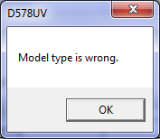 |
This error means you are trying to use the wrong CPS / wrong codeplug / wrong firmware for the model of radio you have. For example, you might be trying to use the 878 CPS with an 878-II radio. You must make sure your CPS software version matches your codeplug file version and matches your firmware version installed in the radio and that you are using it with the correct matching model radio. |
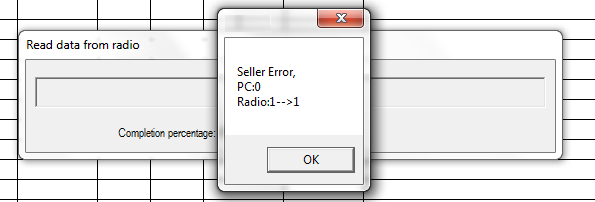 |
If you are getting this cryptic error message when trying to read or write to your radio, it means that your PC programming (CPS) software isn’t the same version firmware as what is on your radio. For example, in the screen grab here, this shows v1.09 software trying to interact with a radio with v1.10 firmware. You must make sure your CPS software version matches your codeplug file version and matches your firmware version installed in the radio and that you are using it with the correct matching model radio. |
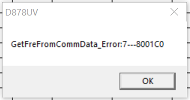 |
If you see this error, or something similar to it, this means your codeplug is corrupt. The solution is to reset the radio, REBUILD your codeplug, and write the rebuilt codeplug to your radio (thanks to Lane KD2TVW for this one) |
 |
This error means your codeplug has become corrupt in memory. All you need do is perform a reset on the radio and reload the codeplug. I also strongly recommend doing a codeplug REBUILD before reloading it to the radio. |
 |
This error is a little more serious. A similar error message is 'Bad Block.’ Try the following, in order:
|
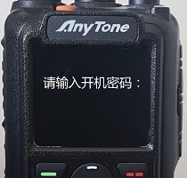 |
This message is asking you to "Please enter power on password:" in Chinese. If you know what the password is, enter it, and then you should reprogram the radio codeplug to reset the radio back in to English language. If you don’t know what the password is, you can reset it using the instructions here |
 |
This error, or ’RTC ERROR!’ or ’RTC not run!’ means that, for what ever reason, the radio can not read the Real Time Clock. There is a tiny internal battery that backs up the Real Time Clock and keeps time when the radio is turned off. If that battery becomes too old, or goes faulty, you may see this error. If you continue to ignore this error message and the battery becomes so bad that it short circuits itself, then that could start to induce other new random errors such as the radio freezing up, not accepting any codeplug or firmware updates, and finally becoming completely unresponsive. A short circuit battery will drag down the microprocessor voltage supply, causing these random failures. The RTC backup battery can be replaced by getting access to the bottom side of the PCB and desoldering the old battery and replacing it with a new MS412FE 3volt lithium battery - just make sure you get a MS412FE already fitted with solder tabs. After fitting, a reset of the radio, setting the time & date and reprogramming the codeplug should set everything right. |
 |
Not really an error message as such, if you are seeing white blocks being displayed instead of an icon after you have made a firmware update, this means you need to also need to do an icon update to the radio. For the 868, the Icon V1.20 update is the most recent and you can download it below. For the 878, the latest Icon V1.21 update can also be downloaded below (Thanks Francesco). For all you DMR-6X2 owners, your latest icon (pic) v1.1b update was included with the v2.01 firmware & CPS package. Once you have downloaded the appropriate package and located the Icon Update folder within, you send the icon / pic .spi file to the radio by using the CPS menu selections Tool > Firmware and Icon Update. Download the ICON update packages here: 878 Icon v1.21 (1003kb): Download via Mega Download via Google Drive Download via Sabercat host 868 Icon v1.20 (822kb): Download via Mega Download via Google Drive Download via Sabercat host 6X2 Pic v1.1b (922kb): Download via Mega Download via Google Drive Download via Sabercat host |
A website with lots of great hints & tips for the AnyTone DMR radio family
(Thanks to Norman M6NBP and lots of others who contributed)
If you can’t find the answer you are looking for here, then this website is a real goldmine of information. It is the accumulation of many user’s experiences, hints and tips for all of the AnyTone DMR radio family. Take a look at:
https://hamradiosouthernrepeaters.co.uk/anytone-dmr.html
Looking for a guide on how to setup APRS? This website shows you how
Alex DO1ALX has created an excellent guide to setting up APRS on the AnyTone radios, take a look at his guide on doing this at:
https://do1alx.de/2021/getting-analog-aprs-to-work-on-an-anytone-at-878uv-and-at-878uvii/
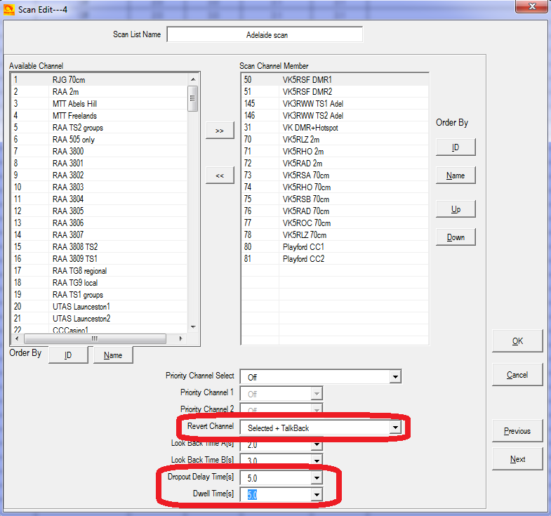
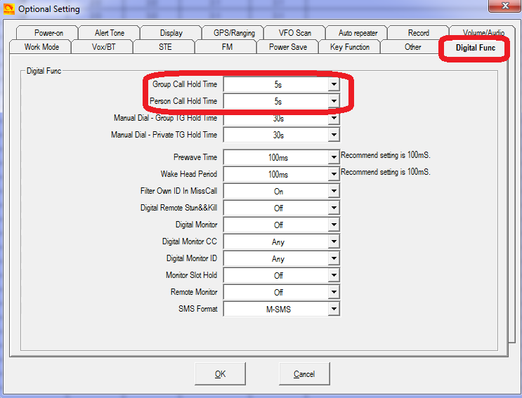
Also make sure your digital call hold times are set to 5 seconds or more:
Hint when using the radio menus
(Credit to Jason VK7ZJA and Jose EB4DOL)
- In large menus with lots of selections, instead of lots of up or down button presses to get to the menu item you want, press the P1 button; this will scroll the menu selection down one entire page of selections, allowing you to get to your desired selection quicker and with fewer button presses.
- The P2 button in menu mode will take you one step back / up in the menu, even if Exit or Back doesn’t appear on the display.
- If you are deep within multiple selections of menus, rather than pushing Back and Exit multiple times to get to the main screen, you can simply push either # or * once to exit the menus and go back to the main screen in one step.
- In VFO mode, you can quickly step up or down in 1 MHz steps using the up / down keypad buttons
- Ensure the radio is updated with baseband version SCT3258 V2.01.07BA or later; AES was not available on earlier versions
- Go to Options > Other > Encryption Type set to AES
- Program in the encryption keys under menu 'AES Encryption Code’ using the same key ID index (Encryption ID) and key value as other radios programmed with AES encryption
- If the key value has less than 64 hex characters, you need to pad out the key with leading zeros
- Finally, in each channel you want to encrypt, select the required key ID index number in the 'AES Digital Encryption’ setting for those channels.
- Note that SMS messages are not encrypted, so be aware of this.
The other encryption type is called 'Common'. This encryption system is set up slightly differently:
- Go to Options > Other > Encryption Type set to Common
- Program in the encryption keys under menu 'Encryption Code’ (not AES Encryption Code) using the same key value
- Finally, in each channel you want to encrypt, select 'Digital Encryption’ setting to on, and select 'Encryption TYPE’ to be the same as other radios in the communication group
Need a spare battery for your AnyTone AT-D868UV, AT-D878UV or BTech DMR-6X2?
If you’re in the United States, there are many options for getting a spare battery available to you. But for those of us outside the USA, options are limited as sellers are reluctant to send just a battery on its own, fearful that the postal system will confiscate a battery not properly packaged to nebulous safety guidelines. I’ve recently had luck ordering from BTech directly and having a battery sent to Australia, which transited the USPS and Australian postal systems and cleared our Customs / Border Protection without problem. Their shipping costs are quite reasonable, too. While I can’t promise that you’ll always have the same successful result in your home country, try shopping (add to cart) with BTech at their website: https://baofengtech.com/purchase#tabs-5
- Turn off GPS, Bluetooth and Roaming
- Keep screen Back Light off permanent, set it for 10, 15 or 20 seconds instead
- Use the lowest RF output power setting for reliable communication. You would be surprised at how well lower power settings work, there is no need to run Turbo or even High power for everything!
- If you don’t need it, turn off / hide the sub-band (Settings > Radio Set > Sub Ch Hide > Sub Ch Off)
- In theory, Power Save is a good idea, and you can set it for a 1:1 or 1:2 ratio, but if you find your radio occasionally locks up or does other strange things for no reason, turn Power Save to off (Settings > Radio Set > Power Save > Off)
- Advanced users might like to use the Test Mode to tune the lowest RF output power setting down to a very low level, say 50mW, for hotspot or close quarters simplex operation
- For the ultimate in power consumption minimisation, also turn off all beeps and turn off the time & date display, and keep screen Back Light level to the minimum - but this is really ’splitting hairs’
- Keep batteries cool. Storage, charging or use above 30°C / 86°F causes lithium ion batteries to rapidly deteriorate. However, also don’t let them freeze.
- Lithium ion batteries don’t like being kept at full charge state, and they don’t like being kept at near empty charge state either.
- If you are not going to use a battery for a while, allow it to half discharge - conveniently with the 868/878 this is indicated just as the battery meter ticks over from three full blocks on the battery meter to two blocks - and store the battery in a cool place
- Avoid frequently fully discharging the battery. Quite unlike what you were used to with NiCd or NiMH batteries where near-fully discharging them was best practice, lithium ion batteries prefer not to be discharged too far, and they are actually quite happy to be frequently cycled with a little discharge then charged a little again.
- Once the battery meter indicates a red battery icon with a lightning bolt, immediately turn off the radio and charge the battery
- For squeezing the very maximum number of charge-discharge-charge cycles out of the 868/878 lithium ion battery, it would be best to only charge them to 75% capacity, or 8.0 volts (the AnyTone charger stops charging at 8.4 volts, or 100% capacity) and then only allow the battery to discharge to 25% capacity, which is about 7.3 volts. Not allowing the battery to fully charge or fully discharge obviously doesn’t make full use of all available battery capacity, but in doing so this stresses the battery less and you will perhaps double the overall number of times or cycles the battery can be used and then recharged. In normal use, a lithium ion battery could be recharged 600-800 times when using the full available capacity of that battery, but by limiting charge to 75% of maximum, and discharging down to no lower than 25% your battery could potentially be recharged 1500 or more times. The big disadvantage of this technique is that it requires the user to carefully manage their battery, and the inconvenience of doing this is high.
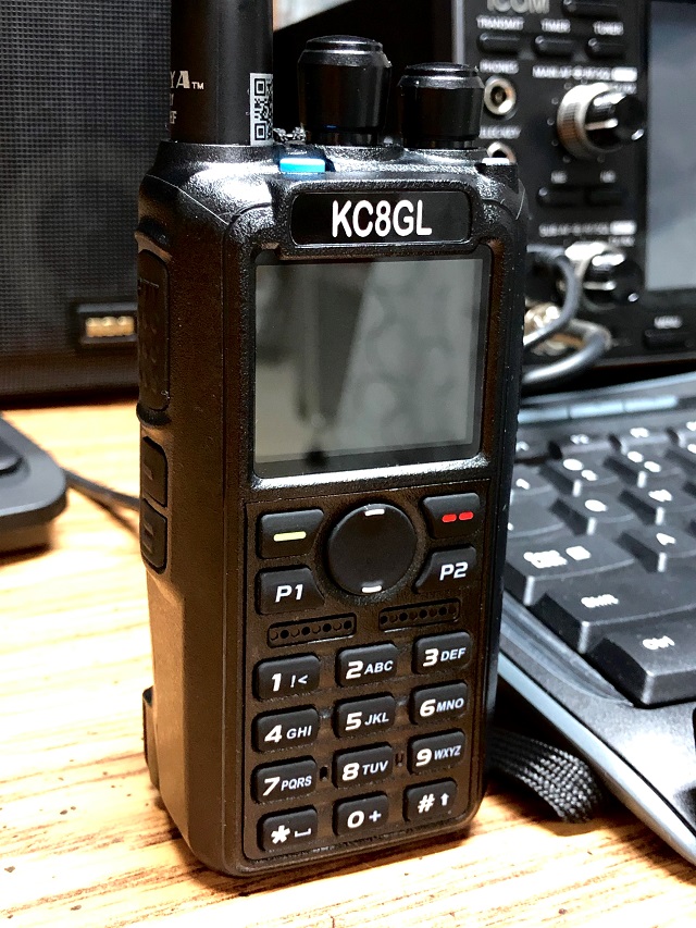
Custom engraved call sign labels for your radio
Thanks to Greg KC8GL, you can order a custom laser engraved self adhesive label for your radio that perfectly fits the AnyTone 868 / 878 or Btech 6X2 radios, at a very attractive price. Greg recommends using a black magic permanent ink marker pen to run a line of ink around the white edge of the labels to help hide the white substrate, touching off that professional look once the label is installed. Also check out the lovely cherry wood callsign display plaques that Greg does. I highly recommend them! Greg is a fantastic guy, quick to respond and happy to answer any questions you may have. See his website at:
https://sites.google.com/view/kc8gl/
3D printed desk stand
If you have access to a 3D printer, with thanks to PrintmasterSteve, here is a design on Thingverse for a desk stand exclusively for the AnyTone 868 / 878 and Btech 6X2:
https://www.thingiverse.com/thing:3141923
Custom background display files for your AT-D878UV
Tim DL2DMC has made available some very nice looking background display files for download, these only work on the 878 of course. If you have made your own background display image and would like to share it with others, please get in touch with me by email and I will place it here for everyone.
http://www.geoo.de/AnytoneDL/D878UVscreens.zip

Chris 2E0UKH has made a video preview of these backgrounds and shows you how to upload them to your radio. Take a peek at his YouTube video here:
https://youtu.be/tPMhNEPVgjw
Guide to the icons & what they mean
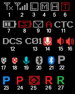
These are the most common icons you will see on the display:
- Received signal, no signal present
- Received signal, full strength
- Low RF output power selected
- Mid RF output power selected
- High RF output power selected
- Turbo RF output power selected
- Battery level indicator
- Battery over discharged, recharge immediately!
- SMS message received & not yet read
- Auto power off timer active - only visible if Bluetooth is off
- CTCSS / PL-tone / sub-tone active on this channel (analogue only)
- DCS / DPL-tone active on this channel (analogue only)
- Colour code number (DMR digital channels only)
- Recording feature active (only works for DMR digital channels)
- Digital monitor single slot mode active (only works for DMR digital channels)
- Digital monitor double slot mode active (only works for DMR digital channels)
- GPS no position fix yet
- GPS position acquired
- VOX turned on
- Bluetooth turned on, no audio device paired
- Bluetooth audio device paired OK
- Bluetooth PTT device not yet paired
- Bluetooth PTT device paired OK
- Bluetooth PTT device battery low
- Encrypted channel (DMR digital channels set with encryption only)
- Roaming searching
- Roaming repeater found

These are written to the radio using the UPDATE MODE:
- Download & unzip this alternate GPS ICON_V1.22_M1 pack (1.2Mb) from one of these locations:
Download via Mega
Download via Google Drive
Download via Sabercat host - Connect the radio to your computer with the programming cable
- Turn on the 878 while holding down PTT & PF2 buttons until UPDATE MODE is displayed
- Start up the CPS software and navigate to menus: Tool > Firmware and Icon Update. If a new Firmware Update window doesn’t automatically open, you can manually find and launch the QX_Update_Firmware.exe application
- Select Open Update File and point the software to the new Icon pack file ICON_V1.22_M1.spi file and click write
- The update takes just over 40 seconds to write, power cycle the radio normally once finished


- First, in the CPS, go to Analog > Analog Address Book and add in each node you might want to be able to quickly recall / dial. The node number goes in the Number column, and the node name / callsign goes under the Name column. This name is what you will see on the radio screen, so it can be given any name that is meaningful to you.
- Then, in Analog > DTMF Setting, set the following:
It is recommended to switch off the side tone, as otherwise you will hear the DTMF tone while transmitting, with full audio level (which could be annoyingly loud).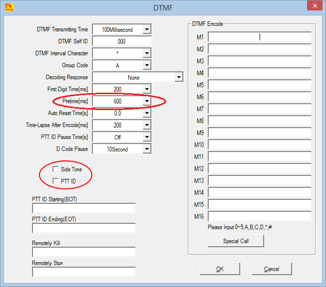
- Next, in Optional Settings > Other, set your Address Book Is Sent With Its Own Code to off.
- The final step is to go in to each channel that is programmed that you will use to connect to your local EchoLink node, and ensure that Optional Signal is set to DTMF.
- Top orange / blue button + PTT for main firmware update mode
- Top orange / blue button + # for DSP SCT update mode (equivalent on Alinco DJ-MD5 is PTT + #)
- Top orange / blue button + PF1 (878 only) enters a ’Record USB mode’ where you can manage playback of recorded DMR audio via the CPS Tool > Record menu, but you need a custom programming cable to do this. Credit to Juan EB2DVG & Francesco IK8JHL
- PTT + PF1 enters the reset radio confirmation menu - but ONLY if this option is enabled in CPS first!
- PTT + PF2 enters a display icon update mode
- PTT + 1 enters test mode where you can select operational bands ("modes") and/or adjust alignment parameters - but ONLY if enabled by use of the AT Options v8 application first!
- PTT + 2 enters a GPS signal strength (RSSI) test mode - only on 878 from firmware V1.10 onward. Credit to IK8JHL
- PTT + 3 enters a GPS module test mode
- PTT + 7 enters an adjustment mode, equivalent to PTT + 1 (Alinco DJ-MD5 only)
- Normally, test mode will be completely inhibited as delivered by the factory
- With 'band select’ test mode, you will only be able to select MODE to change operational frequency bands of the radio
- In full unlocked test mode, some degree of calibration / alignment is possible from the front panel of the radio for deviation levels, power output levels, received signal strength indication (RSSI) levels, squelch levels, frequency fine setting and more.
See the section below Enabling full test / self adjustment mode (click here) for more detail.
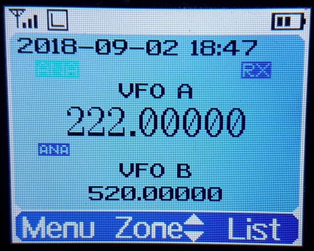
Selecting operational bands
There are many different choices of bands that you can select to use, depending on your radio type & firmware version.
Note that whenever you do change MODE, the radio will reset and you will lose your programmed data. Make sure you have a saved copy of your codeplug. Each saved codeplug will have the MODE it was created under encoded within it. If you try to reload the same codeplug after changing MODE, the CPS software will reject it, saying that it is the wrong band. To fix this, you will need to ’hex edit’ the codeplug rdt file: change byte 0x0011 to match the MODE selected. For example, if you set MODE=00002 then edit your codeplug byte 0x0011 to be hex value 02. Or if you set MODE=00010 then set codeplug byte 0x0011 to hex value 0A.
Note- there is a bug in the CPS programming software: Local Information will not show the correct frequency band the radio is set to, but Model > Model Information does show the correct frequency band
Begin by turning the radio off, then press and hold the PTT and 1 buttons while turning on the radio, hold those two buttons until you see ’TEST MODE’ appear on screen. After releasing the buttons the radio will start up with the text ’MODE:00000’ to the bottom of the screen
If you don’t see this screen, you will need to download AT Options software and enable 'Band select’ check box & write this back to the radio. See:
Download AT Options software
Rotate the top dial to change the mode number, which will select the following:
Standard MODES selectable 878, 878-II, 868, Btech 6X2, Alinco DJ-MD5, Alinco DJ-MD5XGP:
| MODE | 878 v1.27 & 878-II v2.05 RX | 878 v1.27 & 878-II v2.05 TX | 868 v2.40 RX | 868 v2.40 TX | 6X2 v2.04d RX | 6X2 v2.04d TX | DJ-MD5 v1.13e RX | DJ-MD5 v1.13e TX | DJ-MD5X v1.11 RX | DJ-MD5X v1.11 TX |
|---|---|---|---|---|---|---|---|---|---|---|
| 00000 | 400-480 & 136-174 | 400-480 & 136-174 | 400-480 & 136-174 | 400-480 & 136-174 | 400-480 & 136-174 | 400-480 & 136-174 | 400-480 & 136-174 | 400-480 & 136-174 | 400-480 & 136-174 | 400-480 & 136-174 |
| 00001 | 400-480 & 136-174 (12.5k only) | 400-480 & 136-174 (12.5k only) | 420-450 & 144-148 | 420-450 & 144-148 | 400-480 & 144-146 | 400-480 & 144-146 | 400-480 & 144-146 | 400-480 & 144-146 | 430-440 & 136-174 | 430-440 & 136-174 |
| 00002 | 430-440 & 136-174 | 430-440 & 136-174 | 430-440 & 136-174 | 430-440 & 136-174 | 430-440 & 136-174 | 430-440 & 136-174 | 430-440 & 136-174 | 430-440 & 136-174 | 400-480 & 136-174 | 430-440 & 144-146 |
| 00003 | 400-480 & 136-174 | 430-440 & 144-146 | 430-440 & 144-146 | 430-440 & 144-146 | 430-440 & 144-146 | 430-440 & 144-146 | 430-440 & 144-146 | 430-440 & 144-146 | 440-480 & 136-174 | 440-480 & 136-174 |
| 00004 | 434-438 & 144-146 | 434-438 & 144-146 | 440-480 & 136-174 | 440-480 & 136-174 | 440-480 & 136-174 | 440-480 & 136-174 | 440-480 & 136-174 | 440-480 & 136-174 | 440-480 & 144-146 | 440-480 & 144-146 |
| 00005 | 434-447 & 144-146 | 434-447 & 144-146 | 440-480 & 144-146 | 440-480 & 144-146 | 440-480 & 144-146 | 440-480 & 144-146 | 440-480 & 144-146 | 440-480 & 144-146 | 446-447 & 136-174 | 446-447 & 136-174 |
| 00006 | 446-447 & 136-174 | 446-447 & 136-174 | 446-447 & 136-174 | 446-447 & 136-174 | 446-447 & 136-174 | 446-447 & 136-174 | 446-447 & 136-174 | 446-447 & 136-174 | 400-480 & 136-174 | 420-450 & 144-148 |
| 00007 | 400-480 & 136-174 | 420-450 & 144-148 | 446-447 & 144-146 | 446-447 & 144-146 | 446-447 & 144-146 | 446-447 & 144-146 | 446-447 & 144-146 | 446-447 & 144-146 | 400-470 & 136-174 | 400-470 & 136-174 |
| 00008 | 400-470 & 136-174 | 400-470 & 136-174 | 400-470 & 136-174 | 400-470 & 136-174 | 400-470 & 136-174 | 400-470 & 136-174 | 400-470 & 136-174 | 400-470 & 136-174 | 430-432 & 144-146 | 430-432 & 144-146 |
| 00009 | 430-432 & 144-146 | 430-432 & 144-146 | 430-432 & 144-146 | 430-432 & 144-146 | 430-432 & 144-146 | 430-432 & 144-146 | 430-432 & 144-146 | 430-432 & 144-146 | 400-480 & 136-174 | 430-450 & 144-148 |
| 00010 | 400-480 & 136-174 | 430-450 & 144-148 | 400-480 & 136-174 | 430-450 & 144-148 | 400-480 & 136-174 | 430-450 & 144-148 | 400-480 & 136-174 | 420-450 & 144-148 | 400-520 & 136-174 | 400-520 & 136-174 |
| 00011 | 400-520 & 136-174 | 400-520 & 136-174 | 400-480 & 136-174 | 430-440 & 144-146 | 400-480 & 136-174 | 430-440 & 144-146 | 430-440 & 144-148 | 430-440 & 144-148 | 400-490 & 136-174 | 400-490 & 136-174 |
| 00012 | 400-490 & 136-174 | 400-490 & 136-174 | 403-470 & 136-174 | 403-470 & 136-174 | 403-470 & 136-174 | 403-470 & 136-174 | 405-415 & 136-174 | 405-415 & 136-174 | 400-480 & 136-174 | 403-470 & 136-174 |
| 00013 | 400-480 & 136-174 | 403-470 & 136-174 | 400-520 & 220-225 & 136-174 | 400-520 & 220-225 & 136-174 | ||||||
| 00014* | 400-520 & 220-225 & 136-174 | 400-520 & 220-225 & 136-174 | 420-520 & 220-225 & 144-148 | 420-520 & 220-225 & 144-148 | ||||||
| 00015 | 420-520 & 144-148 | 420-520 & 144-148 | 430-440 & 144-147 | 430-440 & 144-147 | ||||||
| 00016 | 430-440 & 144-147 | 430-440 & 144-147 | 430-440 & 136-174 | 136-174 only | ||||||
| 00017 | 430-440 & 136-174 | 136-174 only |
* MODE 14 is not directly selectable on recent 878 firmware versions, you first need to enter a password to enable this band. When MODE and the band number is displayed, press any number on the keypad and the radio will ask "INPUT PASSWORD:" if you happen to know what this password is, enter it, and then you should be able to select MODE 00014.
Then turn off the radio, which will save your selected mode setting, and from that point on, your radio will use the frequency limits that correspond with the mode setting you selected. You can repeat the process to change MODES at any time.
If using AT Options to set the band, this software will automatically do what is necessary to enable MODE 00014, knowledge of the password is not needed.
Note- there is a bug in the CPS programming software: Local Information will not show the correct frequency band the radio is set to, but Model > Model Information does show the correct frequency band
Starting with firmware V1.11 on the 878, fewer MODE options were available to select due to FCC rules governing the sale of radios. This doesn’t mean those other MODES are not actually gone, they’re just not able to be selected. You can use AT Options application to select one of these hidden bands.
I will not be sharing the password for MODE 00014 under any circumstances, as the FCC is starting to closely scrutinise these matters and we don’t want them to revoke the approval status for these wonderful radios, which would result in the AnyTone radios being withdrawn from sale, then nobody would be able to enjoy them.
For the vast majority of users, there is no need to use MODE 00014 anyway. The alternate firmware files available at expanded RX frequencies with alternate firmware will permit reception of the 220 MHz band under any MODE selection, making MODE 00014 redundant.
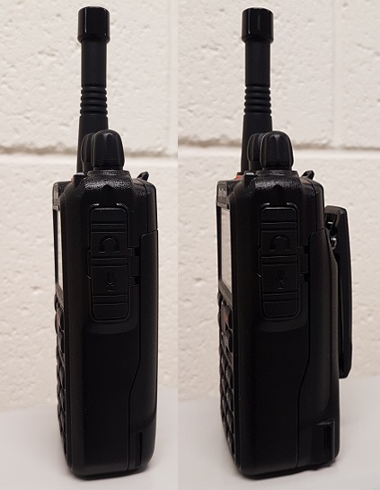
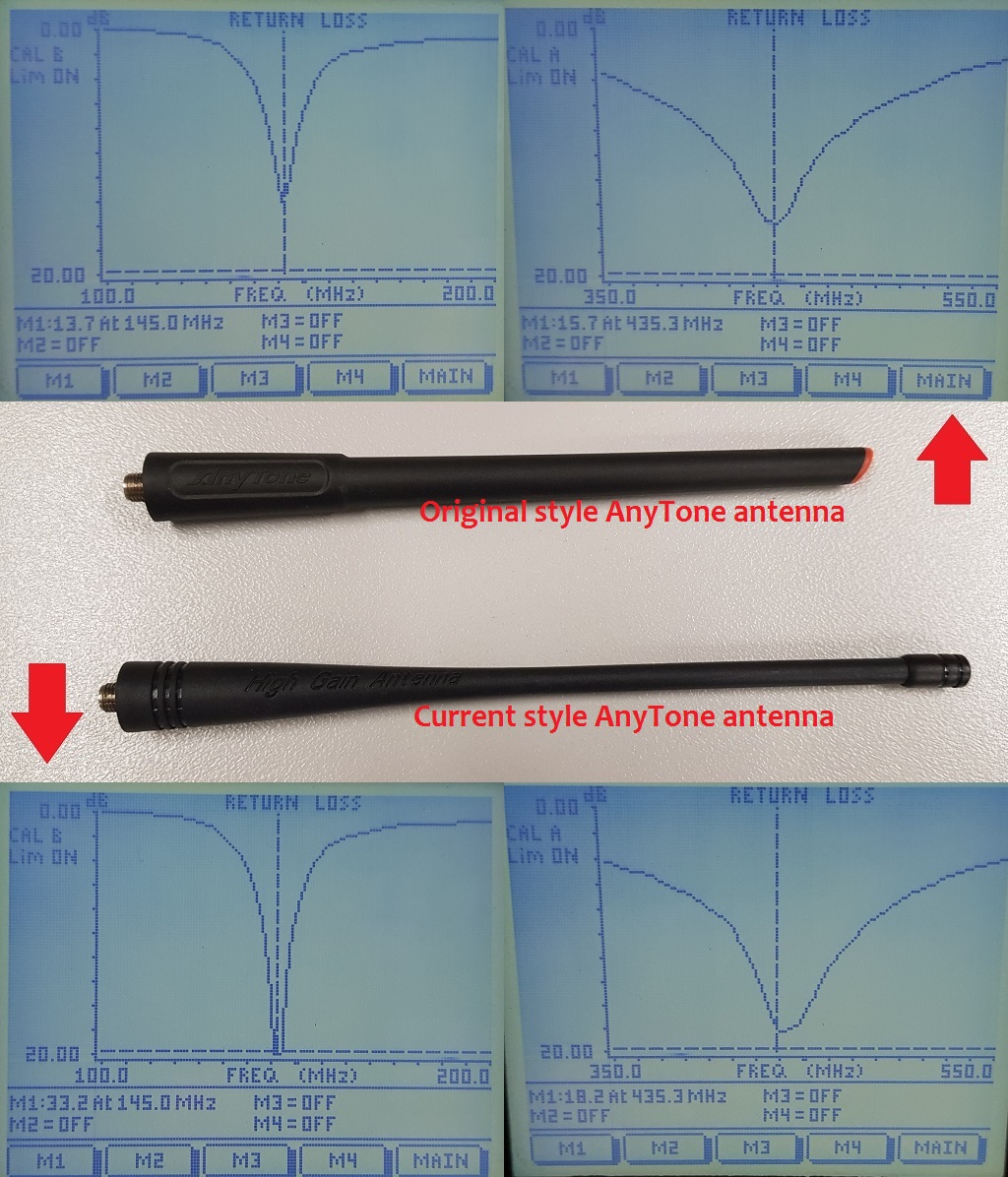
Antennae for the 868 / 878 / 6X2
The ’best’ antenna to use will depend on many things, considerations such as will you be wearing the radio on your belt, or do you want the shortest antenna possible, or do you need a no compromise performance antenna are all questions to be asked in order to work out the best for your use. The following antennae are what I use, and reasons why:
- Very Short: for the shortest possible antenna, they don’t get much smaller than a stubby 1.5 inch long antenna commonly found on eBay with the model number PHD-601. Unlike most other antennae of this length, the PHD-601 is genuinely resonant at both VHF & UHF; the vast majority of antennae around this length are resonant on UHF alone. However due the extreme short length, don’t expect this antenna to work much better than a dummy load. Strictly for very short range contacts only!
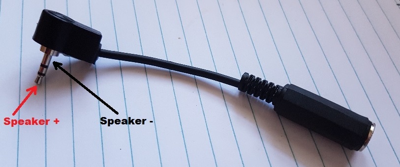
- Short: many people ask what is the antenna I use as seen in the photo above. That is simply a UHF helical stubby antenna about 2.5 inches long, which you can find very cheaply on eBay. They work very nicely on UHF which is where the majority of my operating takes place, but VHF operation is limited to receive only. This antenna looks quite professional, too.
- Short no2: for a genuine dual band short antenna around 3 inches long, the HuaHong HH-S518+ stubby antenna works rather well considering it’s short length, but it is completely inflexible so not suitable for wearing on your belt. Just make sure you get the version with a female SMA connection on the antenna.
- Medium: believe it or not, the stock standard AnyTone dual band antenna that is supplied with the 878 is very good indeed, but if you need something super flexible, a genuine Nagoya NA-666 antenna works just as well, and you’ll hardly notice it when worn on your belt.
- Long: the Comet SMA-24J or NKTech NK-930S are both especially good for VHF, and they are also both super flexible designs, but at 16 inches long are impractical to wear on your belt.
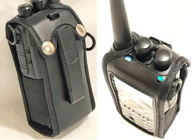
Protective carry case for 868 / 878 / 6X2
PowerWerx have a heavy duty protective carry case for USD $29.99, which looks very professional. View it here:
https://powerwerx.com/csc-868-anytone-atd868uv-nylon-radio-case
GigaParts also sold a similar heavy duty carry case, but no longer does so.
There are generic leatherette carry cases from China on eBay, around the USD $12-15 mark (not including postage) which users report are quite good, and another eBay user jeepbangkok also sells a light duty carry case for around USD $17 (not including postage) which I have and can also report it is quite good too.
Hint when using a Bluetooth earpiece
From Martin G8FXC comes a hint about using a Bluetooth earpiece. He tested a Jabra Bluetooth earpiece which has a feature where the user can redial the last called number by double tapping on the ’answer’ button when used with a cell / mobile phone. When this was paired with the 878, it was found a double tap on the answer button would send the 878 into transmit, and a single tap would return to receive. Martin says he has tried a few different headsets and the only types he found that do this are the Jabra makes with a double tap to answer feature. It has also been found that the Plantronics M25 earpiece also works in this way. If you have a Bluetooth headset or earpiece with a similar feature, give it a try, it might work with your radio in the same way.
How to control playback of recordings using PC software. Easy
With thanks to Francesco
The 868 / 878 has the ability to record DMR transmissions for later play back. Pretty nifty, huh? Did you also know that you can manage the play back of these recordings via PC software? AnyTone produced some software called QXRecord.exe that allows you to view & initiate play back of recordings by the radio. Unfortunately the software doesn’t allow importing of recordings so they can be saved to your PC.
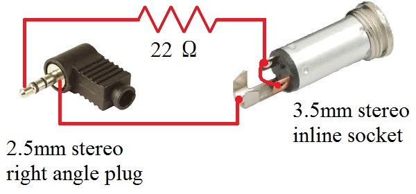
To do this, you need to obtain a second programming cable and modify it by very carefully cutting off just the tip of the 2.5mm connector. This is shown in the video below. Don’t forget that the TYT MD-380 & UV380, Retevis RT3 & RT-3S and Radioddity GD-77 programming cables are the same for the 868/878, so if you have a spare one of those cables you can use & modify that for this purpose.
The QXRecord.exe software hasn’t been included in more recent releases of CPS by AnyTone, so you will need to go looking for earlier releases to find this software, which lives inside the Record directory of your CPS installation.
So, with thanks to Francesco, take a look at his video that shows the modified programming cable, and the QXRecord software in action.
https://www.youtube.com/watch?v=7h1P-4eoF60
How to disassemble the radio / fitting the new Bluetooth module Moderate
Credit to Duane N6DMR
Here is an excellent video, narrated by Duane N6DMR, on how to disassemble the 868 / 878 / 6X2 radio. It goes on to show how the optional Bluetooth module and it’s antenna is fitted, and then reassembly of the radio.
https://www.youtube.com/watch?v=6ZPMJs6bwbQ
Some of my own hints to go along with the video:
- If you are planning on getting a Bluetooth module to fit to your AnyTone, you must ensure that it is a second revision ’V2’ hardware PCB variant with the little plastic press fit connector on the PCB, and that you have (or can make & fit your own) a little metal shield over the SCT3258 IC, as not all radios have this shield fitted already.
- When doing up the screws, first do them up all just a little bit loosely, then after they’re all in place go around and do them up snugly, but not over-tight. This is vital to good RF shielding and overall receiver performance.
- As per the video, re-solder the antenna pin only after you have done the screws up, otherwise the final tightening of the screws and movement of the PCB to snug up to the chassis could place stress on or fracture the soldered antenna pin.
- To ease refitting of the radio chassis into the case, use a little bit of silicon or PTFE lubricant rubbed onto the rubber seal that goes around the chassis edges. This helps the seal slide nicely into the case, rather than it roll out of place and 'bubble’ up between the gap, especially around the bottom.
To carry out this modification do the following:
- Download frequency expanded modified firmware package (6.0Mb) which contains firmware packages for all models 868 / 878 / 878-II / 6X2 / DJ-MD5 / DJ-MD5X from:
Download via Mega
Download via Google Drive
Download via Sabercat host - Unzip the package, and look for your model radio in the folders
- Make sure you have saved your codeplug (rdt) configuration file
- Using the regular firmware updating software & process, send this frequency expanded firmware to the radio.
- If necessary, update your codeplug / rdt configuration file to be compatible with the version of firmware you have downloaded. If you want to reuse your saved codeplug rdt configuration file, you may need to modify one byte with a hex editor as detailed below in italics.
- Enjoy actual extra receive frequency coverage of around 130-178 MHz, 195-290 MHz (with a gap between 200-210 MHz on the 868 & 6X2) and 390-527 MHz (varies from individual radio to radio)
Your mileage may vary of course, due to individual radio & component manufacturing tolerances. You can use the VFO and add memory channels to use these new expanded receive frequency ranges. Sometimes, you can’t enter frequencies via keypad direct entry that start with a 2, 3 or 5 (e.g. any frequency in the 200, 300 or 500 MHz range) the only way to get to them is via lots of knob twisting in VFO mode or use the up/down buttons to tune in 1 MHz steps.
To enter out of band frequencies in the CPS programming software, you will need to use the export-edit-import method: program some dummy channels with valid but easy to recognise frequencies, for example 456 MHz, then use the export feature (tool > export > channel > give it a name > export) and save your exported channels. Open the exported channels file with a text editor - look for your dummy channels you had previously entered, and edit the frequencies as you require, and save the file. Back in the CPS software, use the import feature (tool > import > channel > find your edited csv file > import) to bring the channels with out of band edited frequencies into the radio.
But how do we know it is actually working, not just displaying a frequency and nothing else? Conveniently, the 878 has a quirk that will tell you if the receiver is ’unlocked’ and not working at that frequency: program a button as FM monitor, or turn the squelch level to off. If the radio makes a pulsing or popping noise, the receiver is unlocked and is too far out of band to work. If you hear a constant rush of noise, that indicates the receiver is locked and is working as well as it can do.
If you have a signal generator, you can test that the 878 is actually receiving this signal, or you can use an off air signal to confirm reception is working.
Transmit remains standard according to each MODE. Typically, the receiver locks and actually works around 130-178 MHz, 195-290 MHz (with a gap between 200-210 MHz on 868 / 6X2) and 390-527 MHz, though note that frequencies between 210-400 MHz vary in sensitivity quite a bit.
Also included with the frequency expanded firmware package is an alternate font which can be a bit easier to see than the original. Here is an example of what the new alternate font looks like if you are interested.
AnyTone 868 or 878 or Btech 6X2 or DJ-MD5 on VHF air band?
You’ll notice that this mod will permit coverage of some of the VHF air band. So how well does the radio receive here? Not perfectly since this is strictly an FM & DMR receiver and air band signals are AM. But if you select narrow bandwidth FM and tune off frequency by 2.5 kHz, stronger AM air band signals can be resolved, with some distortion. Take a look at this YouTube video for an example:
https://youtu.be/_F1i_tmPepU
What about 220 MHz, could the 868 / 878 / 6X2 / DJ-MD5 / DJ-MD5X be used on the 1.25 metre band?
You should use the radio for receive only on this band, as the transmitter is not designed for 220 MHz and attempting to transmit on this frequency will place huge stress on, and perhaps damage, the VHF transmit output transistor. In any case power output on 220 MHz is only about 100 milliwatts. Regarding receive on 220 MHz, the 868 is very insensitive in this area, but the 878, while not stellar, is considerably better due to a different receive front end tracking arrangement.
Refer to the sensitivity plots below:
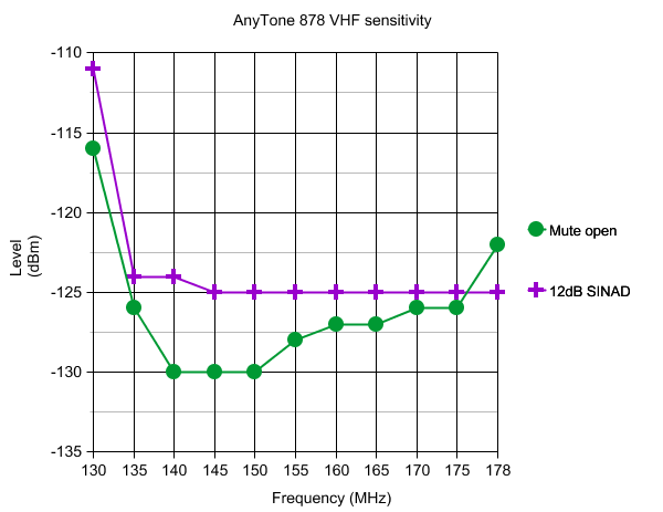
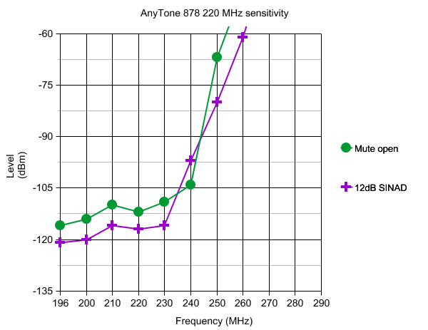
Summary: 0.13uV VHF // 0.32uV 220 MHz // 0.18uV UHF for 12dB SINAD in Narrowband FM.
I heard VHF was deaf on the 878. Is that true?
In a word: no. Some people have complained about the radio being deaf on VHF, but I just can not find any evidence of it.
In the lab, with high grade, calibrated Hewlett Packard RF test gear, the 878 produces excellent VHF sensitivity results, as the sensitivity plots above attest.
In real world tests that I have carried out, connecting a wideband discone antenna fed by LMR-800 cable to the 878 also resulted in VHF sensitivity that was within 1dB of some good quality Kenwood & Yaesu ham handheld radios. Some other lower cost radios lost all ability to receive anything but the very strongest signals in the same test.
It may be possible that such reports of deafness stem from internal noise from the radio making already weak signals sound weaker than they really are. This, and some solutions are covered below in:
Resolving received noise / perceived poor VHF sensitivity issues (improved shielding)
But aren’t all direct conversion receivers rubbish? If direct conversion receivers are rubbish, someone had better inform Motorola and Hytera. Yes, both these top tier manufacturers use direct conversion receivers in their products, including the much vaunted XPR7550 / DP4800 series of radios. So clearly direct conversion receivers are capable of superb performance. While the 878 uses the common AT1846 direct conversion chip, it does have a four pole tunable bandpass filter ahead of the chip, something most other budget handheld radios do not have. Much of the performance of a direct conversion receiver is also dependant upon how well it is configured & set up in software. The 878 has the edge in this regard as well. For example, the 'flutter’ or ’Geiger counter clicking’ that can be heard on strong but varying strength signals of other budget radios also using the AT1846 isn’t anywhere near as noticeable on the 878. This flutter is caused by the direct conversion receiver switching gain profiles to keep signals within proper limits; obviously AnyTone have found a way to achieve this with minimum audio disturbance.
Overall, the AnyTone 878 has a very good receiver, and to get anything better will require you to spend three or four times as much cash.
- Check that you have the receiver set to wideband FM (radio menus: Settings > Chan Set > Band width > Wide) which is the correct mode for listening to most ham activity in the USA and for NOAA signals.
- Turn STE settings to OFF, particularly the ’STE when no signal’ setting (CPS menu: Optional Setting > STE)
Introduction to hex editing. Moderate
Hexadecimal - more commonly abbreviated to just ’hex’ - is a system of counting with sixteen symbols. We humans are used to counting from one to ten with our ten symbols we call numbers, those being 0-9. If we want to go above 9, we join two numbers together e.g. 1 and 0 to be 10, and so on. Hexadecimal begins with 0 and goes up to 9, but instead of moving on to 10, hexadecimal uses letters A through to F, so A in hex would be 10, B=11, C=12 and so on up to F which is equal to 15, then hex "10" is equal to 16, 11 in hex = 17 and so on. Once 19 in hex is reached, the next number is 1A. Get the picture? Have a play around with a scientific calculator to convert hex numbers to decimal numbers, and you’ll soon see how it all works.
OK, so why hex? As you probably know, computers use digital logic circuits which have just two values: on and off. These can be thought of as a 1 or 0, and computers ’talk’ with lots of 1s and 0s - that’s called binary. For us humans to try and make inputs to a computer in binary with just 1s and 0s would be mind-numbingly tedious, but using hexadecimal is a compromise. You’ve probably heard the term 'byte’ before, and it turns out that two hexadecimal numbers fits perfectly into a byte. So 00, 3A, D2 and FF (all examples of hex numbers) can be represented with one byte of memory.
If you were to open a new text document with simply the word "HELLO" in it, and save that text document, you could open the text document in Notepad and edit it at a later time. But that’s not the only way you can edit this text document. By opening the text document in a hex editor application, you can edit the document in it’s raw form as it is stored on your hard disc. What you would see is the word HELLO represented by it’s hex numbers: 48 45 4C 4C 4F. Now lets say you want to change HELLO to APPLE instead. In the hex editor, you would change those hex values to 41 50 50 4C 45, and then save the file.
The advantage of hex editing a file is that it doesn’t matter what created the file or what the file contents are, they all get stored on hard disc the same way, and with hex editing you’re editing the raw data and there are no limitations to making those edits, rather than any artificial limits a program might impose.
One more thing to know before moving on to your first software modification is to know about the concept of little-endian formatting. Little-endian formatting is listing a value with it’s least significant bytes first. Take a number like 490 for example. First break the number up into two bytes: 04 and 90 (add a zero in front of the first number if it’s not already two digits). Now simply reverse the order of the bytes, so that is 90 04. That is little-endian format of (0)490. Another example with a bigger number: 12345678. Broken up into bytes, that’s 12 34 56 78. Now reverse the order of those groups: 78 56 34 12. Not hard, is it? Little-endian formatting can be equally applied to decimal or hex numbers, simply break the number down into two digit groups (i.e. bytes) and then reverse the order of the groups.
To make edits in hex, you’ll want to use a hex editor. It’s just like a word processor, only it edits in hexadecimal. I recommend using a hex editor called HxD. It’s free to download at:
https://mh-nexus.de/en/downloads.php?product=HxD (about 860kb)
Theory behind the frequency expansion mod. Advanced
The age of hardware expansion modification is over, 99% of the time these days software is the route to achieving results. When looking to make frequency expansion modifications by software, the first step is to see if the programming software can accept, or be tricked to accept out of band frequencies; if you can’t send those frequencies to the radio, then modification becomes a lot more difficult. Thankfully, a lot of programming software only checks for valid frequency entry when entering details by hand inside the software. If you edit a saved configuration file, or import frequencies / channels, often this doesn’t go through the software sanity test. The 878 programming software is no exception to this; while out of band frequencies can’t be entered by hand, they can be imported just fine.
The next step is to ensure these out of band frequencies are actually being sent to the radio as intended. For capturing USB data as it is being sent to the radio, WireShark is the go-to tool to analyse USB packets and ensure that the frequencies you want are actually being sent. If the radio accepts and uses these out of band frequencies, you are done and dusted.
In the case of the 878, the firmware inside the radio does have a sanity check going on to trap any frequencies that fall outside permitted limits.
Where a radio is doing a sanity check on a programmed channel’s frequency, it will compare it against a limit that is programmed in to the radio, perhaps as part of its firmware, or perhaps compared against another memory location. In this case, the 878 has multiple limits stored as part of its firmware. These multiple limits are there to set one of the many options of permitted bands. Things become interesting when trying to find out exactly how the radio represents these limits.
One of the essential tools for snooping inside and modifying software like this is something called a hex-editor.
If you need a good hex editor, download HxD in your preferred language here (about 860kb)
Numbers representing frequencies and frequency limits could be stored in one of many ways, including:
- BCD - binary coded decimal. Example: 146.500 MHz might be seen in a hex editor as 01 04 06 05 00 00. That’s quite wasteful on memory, so it could be represented in a ’packed’ form and you would see in a hex editor the following sequence: 14 65 00. The Radioddity GD-77 happens to use this method, combined with little endian format as explained below.
- Direct hexadecimal notation. Continuing to use the example of 146.500 MHz, if we convert this to a kHz value of 146500 kHz, that is equal to hexadecimal 23C44, or if we break it up into bytes as seen by a hex editor: 02 3C 44. More commonly though, the frequency is represented as a value in Hz, as 12.5kHz step frequencies couldn’t be represented with a whole number value in just kHz. So again using our frequency of 146.500 MHz, that’s 146500000 in Hz. Converting that to hex gives 8BB69A0, and broken up into bytes: 08 BB 69 A0.
- Other methods that might be convenient to use: it might be feasible to represent frequencies in a form that is directly used by the frequency synthesis hardware. In PLL schemes, this might be in the form of a 'divider word' that is sent to a programmable divider.
- For radios using the AT1846S 'radio-on-a-chip' they receive data in the form of a hex representation of frequency in kHz x16. Yet again using 146.500 MHz as an example: 146.500 MHz is 146500 kHz, and then multiply by 16 = 2344000 in decimal. Then convert to hex: 23 C4 40. It is possible some radios may store frequencies in a form that can be directly sent to the AT1846S.
It is also worth mentioning that in most systems, a 'little endian' format is used, which simply means to give the lowest significant value byte first. If we have calculated our value as 23 C4 40, then the little endian representation of that is 40 C4 23.
So you can see there could be a variety of methods used to represent frequency values inside software and firmware, and you would have to search for byte patterns for each potential method.
In the case of the 878, none of these methods seem to work, but there is another clue: the .rdt file. After careful examination, you will find that each channel's frequency is stored as a little endian format hex representation of the programmed frequency in Hz divided by 10. Using our example of 146.500 MHz, converting to Hz gives 146500000, and then divide by 10 = 14650000. Now convert to hex: DF 8A 90. And then finally little endian format it: 90 8A DF.
Using this method the 878 stores frequencies in the .rdt 'codeplug'file, we do get some hits if we search for byte patterns of 480 MHz using this method in the firmware .CDD file. Now it's a matter of determining which of those byte groups should be changed. Taking an educated guess, we can assume that the thirteen user selectable band limit frequencies would all be stored together in one area. And so they are!
We can take another educated guess and say that the first lot of bytes in each group indicated correspond to the first user selection in the MODE: 0000x. Now all we need do is to alter those bytes to our new frequency limit. Let's try to go for an upper frequency limit of 527 MHz: 527 MHz = 527000000 Hz, divide by 10 = 52700000, in hex = 03 24 23 60, and finally little endian format = 60 23 24 03. We would replace the first appearance of the representation of 480 MHz (00 6C DC 02) with our new limit of 527 MHz (60 23 24 03).
Sending this modified firmware image to the radio works! You can now tune the VFO above 480 MHz. But now there seems to be another problem: for some reason the tuning stops at 500 MHz exactly (or 520 MHz on the 878). It turns out there is yet another coded limit within the firmware; it assumes the radio will never need to tune above 500 MHz (520 on the 878). We can fix that, too!
Performing another search in the firmware for the representation of 500 MHz (80 F0 FA 02) gives just one hit - this must be it. Change that out for our new limit of 527 MHz (60 23 24 03) and now save that and send to the radio. It works! The radio is now tuning up to 527 MHz.
Incidentally, the 868 also has a lower limit for UHF defined, at 300 MHz. In order for the 868 to tune down to 220 MHz, you have to change this limit as well. Change it out for 210 MHz. Don't try to define a lower UHF frequency limit below 210 MHz as the 868 firmware gets awfully confused and some strange things begin to happen.
The frequency expansion for the 878 is just a little different, because the latest firmware incorporates changes to accommodate a different (Chinese domestic?) version of the radio with 220-250 MHz, the boundary between VHF and UHF has changed from 200 MHz in the 868 to 300 MHz in the 878, starting with firmware v1.07. This means that the bonus expanded frequencies from 190-280 MHz will be part of the VHF band settings. This actually makes the modification just a little easier as we don't have to worry about crossing hard coded band limits.
But how do we know it is actually working, not just displaying a frequency and nothing else? If you have a signal generator, you can test that the 878 is actually receiving this signal. Conveniently, the 878 has a quirk that will tell you if the receiver is 'unlocked' and not working at that frequency: program a button as FM monitor, or turn the squelch level to off. If the radio makes a pulsing or popping noise, the receiver is unlocked and is too far out of band to work. If you hear a constant rush of noise, that indicates the receiver is locked and is working as well as it can do.
Do note that due to the bandpass filtering and front end tracking gain, out of band frequencies between 200 & 400 MHz are not very sensitive, only very strong signals will be heard.
As a final note, when a new version of firmware is released, the addresses at which the changed bytes are written are highly likely to change. You would have to do a fresh search for the byte patterns and replace them appropriately in the new version of firmware.
- Download from this webpage here
- Download via Mega
- Download via Google Drive
- Download via Sabercat host
Be aware that the bitmapped icons and fonts are vertical raster, not horizontal. It could take a lot of scrolling through the file to identify the font, but the auto step feature makes life a lot easier.
In the 868 v2.33 firmware, there are five font sizes: 8x5 H x W (tiny) at 0x06D6F7-0x06D908; 12x10 H x W (medium) at 0x06D921-0x06E1EB; 16x16 H x W (main font) at 0x06E20B-0x06EDC8; and 24x12 H x W (VFO digits) at 0x06EDEF-0x06FB2C. You will also find a fifth and unused super large 24x16 font of numbers and upper case letters only at 0x06FB2D-0x07037E. Other symbols such as the antenna signal meter, battery level meter etc. will be found at 0x07037F-0x070812. Remember, these addresses / locations are only valid for firmware version 2.33, the exact locations will change a little in other versions.

Once you find the location of the font you want to play with, make a note of its starting location. Now you'll want to create a font of the same size. A very useful tool to convert fonts from your computer into bitmaps is Rays Font Editor which you can download here:
Make sure you convert the font to the same size as the one you are going to replace. To use Rays Font Editor to produce a bitmap ready for the 878:
- Install your desired TTF font as a system font on your PC
- Select Capture System Font, then select your desired font from the list
- Select input size by point, and play around with the value to get each character fully visible. Typically the letters M and W are difficult to fit in smaller pixel widths and get truncated at the sides, and lower case letters g, j, p, q and y can get cut off at the bottom: try smaller point values to get the font small enough to fit or manually tweak the problem letters yourself. As an example, the Courier New TTF font works well if imported at 10 point size
- Select Output character size - Change font size and enter height and width to suit the font you are replacing, and click OK
- Examine your characters that have been imported to make sure they all fit nicely and are fully legible. You can edit the appearance and shift characters up/down/left/right to make them look nice.
- Select Font settings, and choose character range starting at 32 and ending at 126, as those are the only characters the 878 needs
- Select Export font. You want to select 'custom', format is binary file, scan direction set to start top-left, scan vertical and leave the other settings as they are. Give your font a name and save it
- Rename the extension of your font from a .dat to .bin and you have a file that's ready to go into the 878.
Once you have a binary image of your desired font, you might want to use Colin's ImageTest application to examine the fonts and confirm how they'll appear on the radio screen.
Now it is simply a case of using your hex editor to copy this binary data from the file you just created over the top of the font data in the firmware file, at the start address you noted earlier. If using HxD, use paste write, not paste insert when copying your new font binary data into the firmware image. Write the firmware to your 878 and enjoy a new look display.
Multi-coloured icons, other than the basic mono-chromatic symbols, are mostly stored in the 868 flash memory locations 0x0015A000 to 0x00200000. The icon update file D868_1G_ICON_V1.11.CDD will write icon data to those memory locations, so it is easiest to edit a copy of this file if you want to customise some of your coloured icons. They are encoded as RGB565 raw bitmap format, and of varying sizes. You could use a raw bitmap viewer to explore the contents of the icon update file. A good website to do this is located at: http://rawpixels.net/
For full screen bitmaps such as the start up image, select a width of 128 pixels, height of 160 pixels, select Flip V, select Predefined format of RGB565, and make sure Little Endian is not selected. For other icons you will need to play around with the width and height, but should use the same settings.
This is what all the standard icons in the 868 look like:
A few other coloured icons are encoded into the firmware image at locations 0x0708A8-0x07166F (v2.33 firmware), the main one used here is the 11x11 digital monitor speaker symbol.
Modify a speaker microphone to keep out DMR pulsed RF feedback. Moderate
(Credit to Owen Duffy VK1OD for this)
If you have a speaker microphone that you like, but is affected by RF feedback from DMR's pulsed RF getting back into it, causing your transmitted audio to become distorted, you can perform modifications to reduce or even eliminate this problem. I have carried out the modifications, adding a SMD capacitor across the speaker microphone electret element, and adding a SMD inductor in line with the positive line of the electret element, and confirm it works very well indeed. See Owen's mods at:
http://owenduffy.net/blog/?p=9326
If you need a good hex editor, download HxD in your preferred language here (about 860kb)
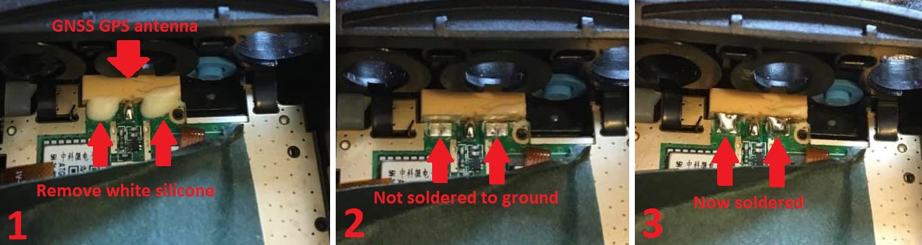
- TLV70133 surface mount 3.3 volt low drop out regulator
- surface mount tantalum capacitor with a value between 100nF & 1uF for C1
- surface mount ceramic capacitor with a value between 1 & 10uF for C2
- very small enamelled copper wire or very fine kynar insulated wire
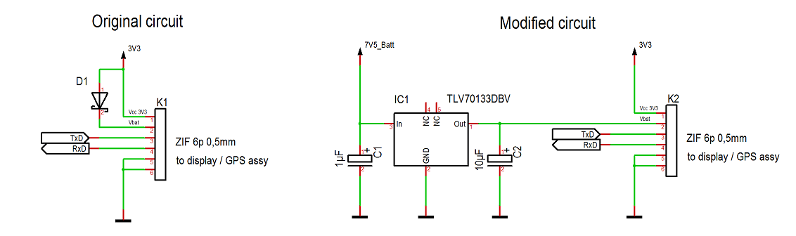
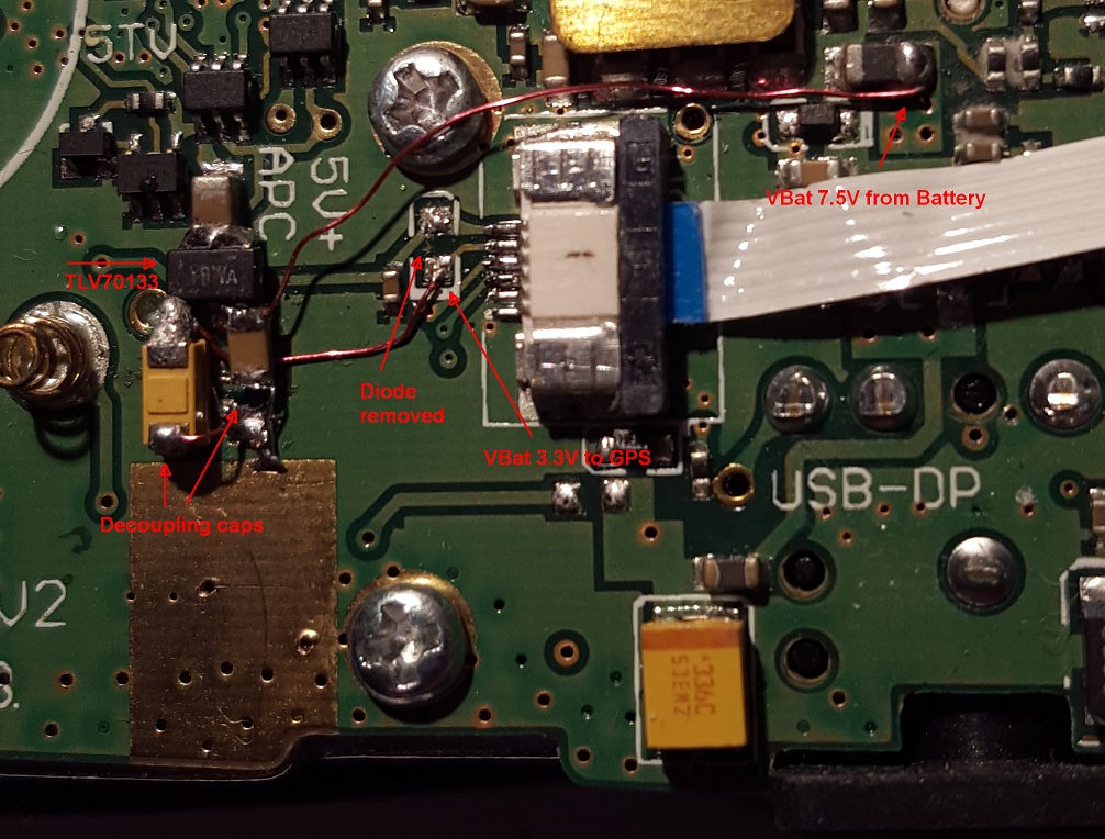
- Download from this webpage here
- Download via Mega
- Download via Google Drive
- Download via Sabercat host
*As always, this software is provided without any warranties, and you use it entirely at your own risk. Using this application to write any changes to your radio is also likely invalidate the manufacturer's warranty
The application is suitable for the AnyTone 878, 878-II, 868, AnyTone 578 of all flavours, Btech 6X2, Alinco DJ-MD5 & DJ-MD5X, Alinco DR-MD500 & DR-MD520 of all flavours, but NOT the Radioddity GD-AT10G at this stage.
Ensure that you do not have any power on password active. If you do, you must use the CPS software to remove it first. Use of AT Options while a power on password is active can, under certain circumstances, cause some data to be overwritten with default data.
When you run the software, select your Com port and READ from the radio. Then edit any text fields you may want, and make sure Band Select and Full Test Mode check boxes are ticked. Finally, WRITE the settings back to the radio - this only takes a fraction of a second to do, and the radio will reboot. It may take a few extra seconds more than normal to boot up, this is OK as it is reconfiguring internal memory.
To activate test mode, turn off the radio, hold down the PTT + keypad 1 buttons until TEST MODE is displayed on the radio screen, then let the two buttons go. The radio will boot up into it's full test / self adjustment mode.
Once you start test mode, scroll up and down between different test adjustment points using the zone up/down button. The following adjustments are available:
I strongly recommend you go through each setting and write down what they are before making any adjustments
| CH | 868 Setting | Adj. range | 868 Description | 878 / 6X2 Setting | Adj. range | 878 / 6X2 Description |
|---|---|---|---|---|---|---|
| 1 | nil | nil | Low UHF test frequency | nil | nil | Low UHF test frequency |
| 2 | nil | nil | Mid UHF test frequency | nil | nil | Mid UHF test frequency |
| 3 | nil | nil | High UHF test frequency | nil | nil | High UHF test frequency |
| 4 | nil | nil | Low VHF test frequency | nil | nil | Low VHF test frequency |
| 5 | nil | nil | Mid VHF test frequency | nil | nil | Mid VHF test frequency |
| 6 | nil | nil | High VHF test frequency | nil | nil | High VHF test frequency |
| 7 | FQCU | 0-65535 | Frequency fine tune | FQCU | 0-65535 | Frequency fine tune |
| 8 | PAHU | 0-255 | UHF RF power output turbo setting | PATU | 0-255 | UHF RF power output turbo setting |
| 9 | PAMU | 0-255 | UHF RF power output high setting | PAHU | 0-255 | UHF RF power output high setting |
| 10 | PALU | 0-255 | UHF RF power output medium setting | PAMU | 0-255 | UHF RF power output medium setting |
| 11 | PASU | 0-255 | UHF RF power output low setting | PALU | 0-255 | UHF RF power output low setting |
| 12 | MODU | 0-255 | Overall deviation setting for both UHF & VHF (value copied to 39 below) | MODU | 0-255 | Overall deviation setting for both UHF & VHF (value copied to 40 below) |
| 13 | TONEU | nil | Push PTT to transmit a test 1000 Hz tone on a UHF FM frequency | TONEU | nil | Push PTT to transmit a test 1000 Hz tone on a UHF FM frequency |
| 14 | CTCW | 0-63 | Deviation setting for CTCSS in both UHF & VHF (value copied to 41 below) | CTCW | 0-63 | Deviation setting for CTCSS in both UHF & VHF (value copied to 42 below) |
| 15 | DCSW | 0-63 | Deviation setting for DCS in both UHF & VHF (value copied to 42 below) | DCSW | 0-63 | Deviation setting for DCS in both UHF & VHF (value copied to 43 below) |
| 16 | RXVLU | 0-4095 | UHF receive tracking gain, low end of band | RXVLU | 0-4095 | UHF receive tracking gain, low end of band |
| 17 | RXVMU | 0-4095 | UHF receive tracking gain, mid band | RXVMU | 0-4095 | UHF receive tracking gain, mid band |
| 18 | RXVHU | 0-4095 | UHF receive tracking gain, top end of band | RXVHU | 0-4095 | UHF receive tracking gain, top end of band |
| 19 | SQTHU | 60-134 | UHF squelch threshold | SQTHU | 60-134 | UHF squelch threshold |
| 20 | RSSIU | nil | UHF RSSI, inject RF at desired level for 1 bar reading, rotate top dial to sample and lock in value | RSSIU | nil | UHF RSSI, inject RF at desired level for 1 bar reading, rotate top dial to sample and lock in value |
| 21 | A OBHU | 0-65535 | not yet known, but seems to adjust screen brightness (suspect this is a bug) | A OBHU | 0-65535 | not yet known |
| 22 | A OBLU | 0-65535 | not yet known | A OBLU | 0-65535 | not yet known |
| 23 | D OBHU | 0-65535 | not yet known, unable to adjust from test menu | D OBHU | 0-65535 | not yet known |
| 24 | D OBLU | 0-65535 | not yet known, unable to adjust from test menu | D OBLU | 0-65535 | not yet known |
| 25 | D CTCW | 0-65535 | CTCSS deviation level in A+D mode | D CTCW | 0-65535 | CTCSS deviation level in A+D mode |
| 26 | D DCSW | 0-65535 | DCS deviation level in A+D mode | D DCSW | 0-65535 | DCS deviation level in A+D mode |
| 27 | DIGIU FSKL | nil | Push PTT to send test FSK signal (heard as 2400 Hz) at low end of UHF band | DIGIU FSKL | nil | Push PTT to send test FSK signal (heard as 2400 Hz) at low end of UHF band |
| 28 | DIGIU FSKM | nil | Push PTT to send test FSK signal (heard as 2400 Hz) at mid UHF band | DIGIU FSKM | nil | Push PTT to send test FSK signal (heard as 2400 Hz) at mid UHF band |
| 29 | DIGIU FSKH | nil | Push PTT to send test FSK signal (heard as 2400 Hz) at high end of UHF band | DIGIU FSKH | nil | Push PTT to send test FSK signal (heard as 2400 Hz) at high end of UHF band |
| 30 | DIGIU 600Hz | nil | Push PTT to send test 600Hz signal UHF band (heard on FM as 200 & 400 Hz?) | DIGIU 600Hz | nil | Push PTT to send test 600Hz signal UHF band (heard on FM as 200 & 400 Hz?) |
| 31 | DIGIU 300Hz | nil | Push PTT to send test 300Hz signal UHF band (heard on FM as 800 Hz?) | DIGIU 300Hz | nil | Push PTT to send test 300Hz signal UHF band (heard on FM as 800 Hz?) |
| 32 | DIGIU 1031 | nil | Push PTT to send test signal UHF band, heard on DMR as 1031 Hz | DIGIU 1031 | nil | Push PTT to send test signal UHF band, heard on DMR as 1031 Hz |
| 33 | DIGIU BER | nil | Display received BER of DMR test signal | DIGIU BER | nil | Display received BER of DMR test signal |
| 34 | DIGIU TEST | nil | Test UHF DMR for both TX & RX as if it were on a regular DMR channel | DIGIU TEST | nil | Test UHF DMR for both TX & RX as if it were on a regular DMR channel |
| 35 | PAHV | 0-255 | VHF RF power output turbo setting | PATV | 0-255 | VHF RF power output turbo setting |
| 36 | PAMV | 0-255 | VHF RF power output high setting | PAHV | 0-255 | VHF RF power output high setting |
| 37 | PALV | 0-255 | VHF RF power output medium setting | PAMV | 0-255 | VHF RF power output medium setting |
| 38 | PASV | 0-255 | VHF RF power output low setting | PALV | 0-255 | VHF RF power output low setting |
| 39 | MODV | 0-255 | Overall deviation setting for both VHF & UHF (value copied to 12 above) | PAMV_2 | 0-255 | 222 MHz RF power output medium setting |
| 40 | TONEV | nil | Push PTT to transmit a test 1000 Hz tone on a VHF FM frequency | MODV | 0-255 | Overall deviation setting for both VHF & UHF (value copied to 12 above) |
| 41 | CTCWV | 0-63 | Deviation setting for CTCSS in both UHF & VHF (value copied to 14 above) | TONEV | nil | Push PTT to transmit a test 1000 Hz tone on a VHF FM frequency |
| 42 | DCSWV | 0-63 | Deviation setting for DCS in both UHF & VHF (value copied to 15 above) | CTCWV | 0-63 | Deviation setting for CTCSS in both UHF & VHF (value copied to 14 above) |
| 43 | RXVLV | 0-4095 | VHF receive tracking gain, low end of band | DCSWV | 0-63 | Deviation setting for DCS in both UHF & VHF (value copied to 15 above) |
| 44 | RXVMV | 0-4095 | VHF receive tracking gain, mid band | RXVLV | 0-4095 | VHF receive tracking gain, low end of band |
| 45 | RXVHV | 0-4095 | VHF receive tracking gain, top end of band | RXVMV | 0-4095 | VHF receive tracking gain, mid band |
| 46 | SQTHV | 60-134 | VHF squelch threshold | RXVHV | 0-4095 | VHF receive tracking gain, top end of band |
| 47 | RSSIV | nil | VHF RSSI, inject RF at desired level for 1 bar reading, rotate top dial to sample and lock in value | SQTHV | 60-134 | VHF squelch threshold |
| 48 | A OBHV | 0-65535 | not yet known | RSSIV | nil | VHF RSSI, inject RF at desired level for 1 bar reading, rotate top dial to sample and lock in value |
| 49 | A OBLV | 0-65535 | not yet known | A OBHV | 0-65535 | not yet known |
| 50 | D OBHV | 0-65535 | not yet known | A OBLV | 0-65535 | not yet known |
| 51 | D OBLV | 0-65535 | not yet known | D OBHV | 0-65535 | not yet known |
| 52 | DIGIV FSKL | nil | Push PTT to send test FSK signal (heard as 2400 Hz) at low end of VHF band | D OBLV | 0-65535 | not yet known |
| 53 | DIGIV FSKM | nil | Push PTT to send test FSK signal (heard as 2400 Hz) at mid VHF band | DIGIV FSKL | nil | Push PTT to send test FSK signal (heard as 2400 Hz) at low end of VHF band |
| 54 | DIGIV FSKH | nil | Push PTT to send test FSK signal (heard as 2400 Hz) at high end of VHF band | DIGIV FSKM | nil | Push PTT to send test FSK signal (heard as 2400 Hz) at mid VHF band |
| 55 | DIGIV 600Hz | nil | Push PTT to send test 600Hz signal VHF band (heard on FM as 200 & 400 Hz?) | DIGIV FSKH | nil | Push PTT to send test FSK signal (heard as 2400 Hz) at high end of VHF band |
| 56 | DIGIV 300Hz | nil | Push PTT to send test 300Hz signal VHF band (heard on FM as 800 Hz?) | DIGIV FSKH2 | nil | Push PTT to send test FSK signal (heard as 2400 Hz) at 222 MHz band |
| 57 | DIGIV 1031 | nil | Push PTT to send test signal VHF band, heard on DMR as 1031 Hz | DIGIV 600Hz | nil | Push PTT to send test 600Hz signal VHF band (heard on FM as 200 & 400 Hz?) |
| 58 | DIGIV BER | nil | Display received BER of DMR test signal | DIGIV 300Hz | nil | Push PTT to send test 300Hz signal VHF band (heard on FM as 800 Hz?) |
| 59 | DIGIV TEST | nil | Test VHF DMR for both TX & RX as if it were on a regular DMR channel | DIGIV 1031 | nil | Push PTT to send test signal VHF band, heard on DMR as 1031 Hz |
| 60 | VBAT | 0-200 | Calibrate displayed voltage of battery | DIGIV BER | nil | Display received BER of DMR test signal |
| 61 | MODE | 0-12 | Changes operational frequency bands of radio | DIGIV TEST | nil | Test VHF DMR for both TX & RX as if it were on a regular DMR channel |
| 62 | 087.50M | nil | Receiver test of FM broadcast band | VBAT | 0-200 | Calibrate displayed voltage of battery |
| 63 | 097.50M | nil | Receiver test of FM broadcast band | F1 ParaA0 | 0-65535 | Hex BCD combined mic gain & mic AGC values at 65 & 66 below, changing has no effect |
| 64 | 108.00M | nil | Receiver test of FM broadcast band | REG0 | 0-FFFF | If set correctly will copy 32 bytes of firmware to memory just above RF cal data, use unknown |
| 65 | MIC | 0-95 | Microphone gain, but does not appear to have any effect | |||
| 66 | AGC | 0-95 | Microphone dynamic auto gain for DMR, but does not appear to have any effect | |||
| 67 | MODE | 0-17 | Changes operational frequency bands of radio | |||
| 68 | 087.50M | nil | Receiver test of FM broadcast band | |||
| 69 | 097.50M | nil | Receiver test of FM broadcast band | |||
| 70 | 108.00M | nil | Receiver test of FM broadcast band |
For the squelch threshold values, a higher value gives a more sensitive squelch. Typically little to no improvement in squelch sensitivity is obtained with values higher than about 115, but some users have reported improvement with higher values. Lower values require progressively stronger signals to open the squelch.
The RSSI (received signal strength indicator - in other words the signal meter) has a fairly compressed range of 15dB. I'd have preferred to see at least 30dB range in the signal meter, but I've found an acceptable compromise has been to set one bar at -113dBm which equates to values of RSSIU of 36 and RSSIV of 39. The signal meter then reads:
- 1 bar -113 dBm or about S-5
- 2 bars -108 dBm or about S-6
- 3 bars -103 dBm or about S-7
- 4 bars -98 dBm or about S-9
Once finished changing your values, turn the radio off and on again to save them to memory. If you like, you can disable full test mode again by de-selecting the Full Test Mode check box in AT Options application and writing back to the radio. Or, you can de-select both Full Test Mode and Band Select check boxes, which will totally inhibit test mode completely. The values you changed or adjusted will not be erased by doing this, it simply prevents you from accessing the full test mode and inadvertently changing them again. These values will not be overwritten, changed or restored to default by resetting of the radio. Once you change them, you can not get the original value back unless you wrote it down before making adjustments.
Finally, as you go through the adjustment values, it becomes apparent that the 878 (only) has adjustments for the 222 MHz band. Do not attempt to use these radios on that band for TX as the hardware is not designed for it.
- Power up the radio and wait until it asks for the password.
- Connect your programming cable, and using the CPS software, read from the radio.
- Go to the CPS menu: Optional Setting > Power-on > Power-on Password Char and you will see what your password is set to. Record your password somewhere safe if you intend to continue using a power on password.
- If you wish to remove the password check, delete every digit in the Power-on Password Char field, save the codeplug, and write it back to the radio.
- Power cycle the radio again and confirm you are not asked for a password this time.
If your password has become corrupted in memory and the password read is anything other than pure digits, and over-writing or deleting the password does not work, then your only option is to do a full defrost of the radio. A quick defrost will not work.
- Turn off your clock display and GPS. It appears as if any display updates or GPS data that is multiplexed on the data lines connecting the display front half of the radio to the main PCB will cause some interference on VHF. The primary culprit for this is the clock flashing colon between the hours and minutes. Updating to firmware version 2.33 or later can help, as this stops the colon / time separator symbol from flashing.
- Noise from display. The majority of noise appears to come from the LCD itself, and in later revisions of the radio, AnyTone reduced this noise by earthing the metal frame that surrounds the display. You can see this indicated by two small grey arrows in the picture of the display / GPS PCB a little bit further down. If your display doesn't have this, then thoroughly scrape the paint from the two metal tabs poking through the bottom of the display PCB and solder them to the ground plane as pictured. Use a 60-100 watt soldering iron to rapidly heat the components and solder quickly. Use of a smaller iron will take longer to heat components up which allows time for the heat to spread further, and that isn't ideal.
- Chassis to PCB shielding: A good connection between the PCB earth and the chassis will ensure the best RF shielding possible. Critical for this good connection, you should ensure that all screws are done up snugly, but not so tight that they will strip the threads.
- New metal shield over the SCT3258 IC: Appearing in the 878 radio is a small sheet metal shield fitted over the SCT3258 IC, as seen in this screen grab from the Bluetooth module fitting YouTube video mentioned earlier. This shield isn't fitted to all radios, and it isn't known if this on it's own helps with RF shielding. But if you do fit the Bluetooth module, ensuring this shield is in place is vital to ensure the Bluetooth RF transmissions don't interfere with the operation of the SCT3258, and to provide a physical mounting point for the Bluetooth antenna. I made my own shield out of tin plate. The shield only needs to sit about 1.5mm above the PCB, which allows just enough clearance for components, and a layer of electrical insulating tape on the underside of the shield. Allow a generous clearance around the screw holes at the bottom corner of the radio.
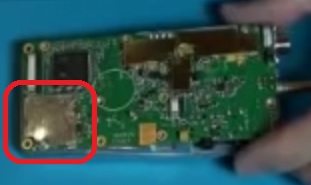
- Nickel shielding spray paint. (Only for the really keen & fastidious radio operator: very extensive disassembly!) While AnyTone have done a reasonable job of shielding sensitive parts of the circuitry with brass shields and the cast aluminium chassis, you can amp up the shielding by use of nickel shielding spray. If you look inside some cellular mobile phones or portable two way radios, you will sometimes see a coating of paint on the inside of any plastic parts. This paint could be black, brown, pink, grey or silver, and they all have a similar job: they're conductive and add a thin layer of RF shielding to the electronics inside. Electrolube's NSCP400H nickel spray paint is sold by Element14 (Farnell) is made exactly for this job.
You might be able to find alternative products from other suppliers but do not use any of the carbon based conductive / EMI / RFI shielding paints, they are simply not good enough. Even with fancy sounding names like 'nano-impregnated' they can't compare to nickel, copper or silver based shielding paints. The carbon based paints are usually distinguishable by their very dark grey, almost black colour, so avoid any paint like that.
You'll need to follow these general steps:- Completely disassemble the front half of the radio. You need a bare plastic shell with the LCD display, orange / blue top button and side PTT buttons removed and the plastic 'light pipe' for the top mounted TX/RX LED removed as well. The speaker and keyboard can remain in place.
- There will be two ribbon cables coming out of the back of the keypad, don't try to remove these, leave as is for the moment.
- Part of the bottom ribbon cable connects to the electret microphone insert. Desolder the ribbon cable from the insert.
- Use masking tape to cover every surface that you don't want the nickel spray paint to go. That not only includes ALL the visible exterior parts, but also many interior areas as well. This job of masking every surface you don't want covered by the paint is fiddly and tedious in the extreme, but is necessary because the spray paint will go everywhere, trust me!
- Cut out a circle of paper to fit over the speaker and use masking tape to neatly hold it over the back of the speaker. Use a small square of making tape to cover the back of the electret microphone insert.
- Also cut out a rectangle of cardboard to the same size as the LCD clear display window lens. It is best not to use masking tape directly on the display lens or anything with printing, cover those with some paper or cardboard and hold in place with masking tape over the top.
- Block up any openings such as the top & side button openings with cotton wool - I use craft work decorative soft balls for this and it works well.
- You will also need to leave the area around the GPS antenna clear of any coating, so mask up that area on the inside of the case as well, just behind and above the AnyTone label.
- Mask up the two ribbon cables coming out of the back of the keypad, and cover the little conductive contacts with paper so the masking tape doesn't leave any residue on these.
- Use some toothpicks to block up the four screw holes in the chassis, and cut them off so only a little bit pokes out of the screw hole.
- Finally, also mask up around a slight raised lip on the inside edge of the casing, where the rubber seal seats in the casing. The rubber seal is a very tight fit and you don't want to make that any tighter from a coating of nickel shielding paint, see the photos to see how this is done.
- Nickel spray paint is known to be rather hazardous. You will want to do this job outside, and on a calm wind free day. Wear goggles, dust mask, long sleeve shirt and rubber gloves.
- Place the masked up shell onto a piece of scrap cardboard and use good spray painting techniques to apply a thin coat of nickel spray on the inside of the shell. The spray will look uneven as you apply it, and don't let that tempt you into applying more paint in those areas. Too much paint will attack the plastic and cause the coating to crack once dried.
- Let the coat of nickel paint dry, about 24 hours.
- If need be, apply one more thin coat of nickel paint to cover any areas that were missed or uneven, and let dry for another 24 hours.
- Slowly remove any masking tape, cardboard protective bits and cotton wool stuffing, and pull out the toothpicks from the screw holes. You should have your same bare radio shell but with a nice grey coating of nickel spray paint on the inside.
- Reassemble the radio. Don't forget to wipe over the LCD screen and inside of the display lens with a good quality lint-free optical cleaning cloth before refitting the display board. Combining this nickel spray paint shielding with copper foil tape over the ribbon cables (details just below) provides the most benefit and greatest noise reduction.
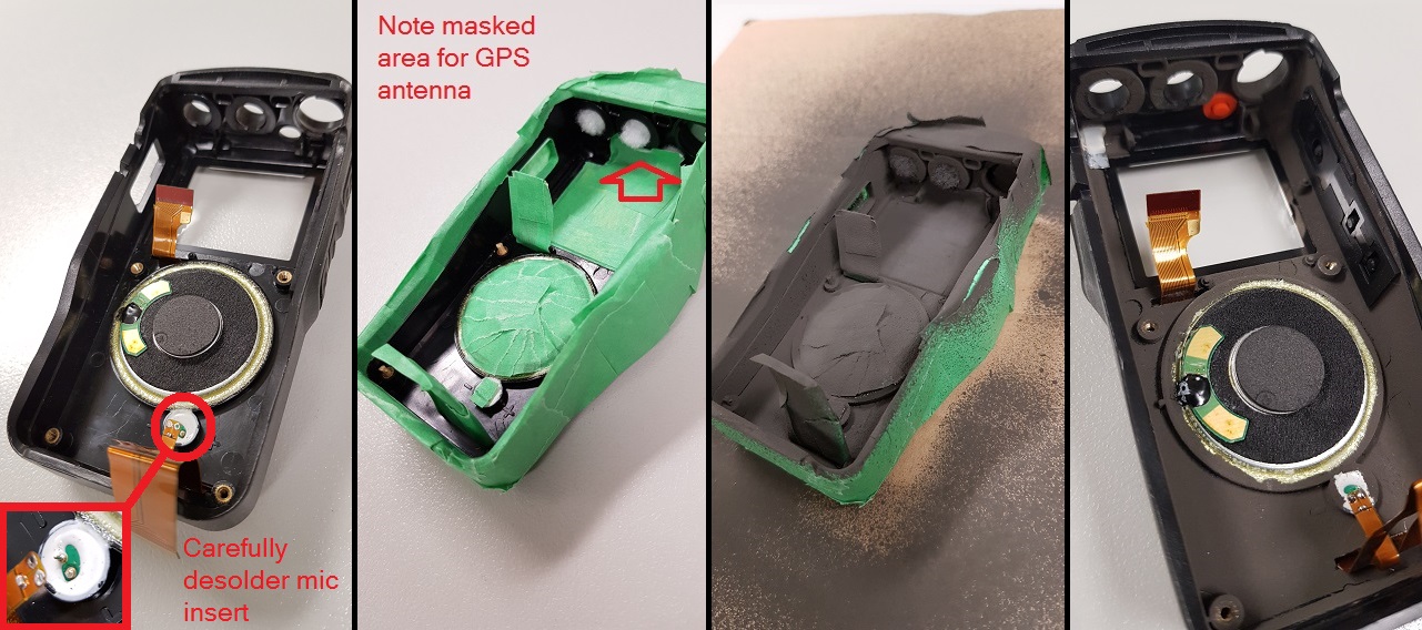
- Don't coat the rectangular rubber piece that fits over the side speaker/mic connectors, these must be left 'floating' from ground. This nickel coating will give an extra 10dB worth of shielding to the back side of the main PCB, which results in a 'cleaner' receiver, especially in an area of moderate RF fields: weaker signals are less distorted and less disturbed by nearby transmitters in comparison to a radio without this treatment. The most noticeable improvement, however, is the receiver picks up far less 'birdies' (internally generated signals)
Note for those planning to, or already have, Bluetooth fitted: the extra shielding offered by the nickel screening spray paint will have a detrimental effect on the Bluetooth signal getting in and out of your radio. Some signal will still leak out, but Bluetooth range will be decreased (by how much remains to be seen).
- Shielding the small flat flexible ribbon cable with some adhesive copper tape helps a little bit, according to Colin G4EML, especially if you have the older white style flat flexible ribbon cable. It is also essential that you insulate the copper shielding to prevent any shorts circuits, clear plastic sticky tape is fine. If you have a brown cable with no tracks visible on the back side as indicated by the single grey arrow in the picture of the display / GPS PCB a little bit further down, your cable is already upgraded and won't benefit much from any adding any extra shielding to the cable.
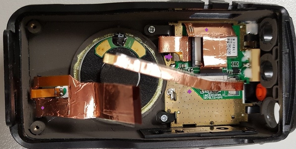
- Adding more RF gaskets In the picture above, see the little silver-grey sponge like thing indicated by the small purple arrow? That is called a 'RF gasket' and is used to ensure a positive earth connection between two surfaces. Here, AnyTone have fitted one to earth the shielded back side of that ribbon cable to the PCB ground plane. If you've taken the time to shield the ribbon cables with copper tape as per the point above, then you can add more RF gaskets in to earth them too, rather than leave them 'floating' from earth. (They won't really be entirely floating as they will get a little bit of capacitive coupling to earth, but this trick will ensure they are definitely very well earthed) This takes a little bit of planning, as you don't want to insulate the copper tape in the area where it is going to be making contact with the RF gasket, and nor do you want the RF gasket to short out anything nearby when it is compressed down and spreads out. I added four new RF gaskets to the radio:
- Main ribbon near the microphone insert, adding the RF gasket just where it exits the slot in the front case. This relies on the front case being treated with the nickel shielding spray paint first.
- Longer & wider ribbon for the display, again adding a little RF gasket just where it exits the slot of the display PCB.
- Skinny little ribbon, adding a RF gasket on to the PCB near where the earth plane on the PCB is at a diagonal angle close to the white 'D878LCD+GPS' printing. Ensure the ribbon cable is insulated it's entire length except for the small area where it makes contact with the RF gasket here, you don't want it to short out the components just above the white printing on the display PCB, or on the main PCB. Afterward, the thicker green insulating pad is used to help hold the skinny ribbon cable in place so that it lays over the top of this RF gasket.
- Last RF gasket goes on the RF shield of the main PCB close to the PTT side PCB, so it makes contact with the display LCD when they come together once the radio is reassembled. Some radios may have this RF gasket fitted by the factory already; mine did not.
- Shielding the small flat flexible ribbon cable with some adhesive copper tape helps a little bit, according to Colin G4EML, especially if you have the older white style flat flexible ribbon cable. It is also essential that you insulate the copper shielding to prevent any shorts circuits, clear plastic sticky tape is fine. If you have a brown cable with no tracks visible on the back side as indicated by the single grey arrow in the picture of the display / GPS PCB a little bit further down, your cable is already upgraded and won't benefit much from any adding any extra shielding to the cable.
- https://fccid.io/T4KD868UV shows a first revision 'V2' hardware with GD32F303VE 512k MCU
- https://fccid.io/2AGND-DMR6X2 less information here, but the approval refers back to the T4KD868UV approval
- https://fccid.io/T4KD878UV shows a second revision 'V2' hardware with GD32F303VG 1024k MCU
Notice that the 878 approval documents also include details of an older model Bluetooth module. This older model Bluetooth module uses the Beken BK3260 Bluetooth IC, and it also has a Beken BK2452 2.4GHz Wi-Fi IC installed as well, though it doesn't have an antenna connected. The Bluetooth function will allow wireless audio connectivity to the radio so you can use it with a Bluetooth hands free kit for example, for wireless receive and transmit audio and PTT.
https://fccid.io/PH3DJ-MD5 details the Alinco DJ-MD5.
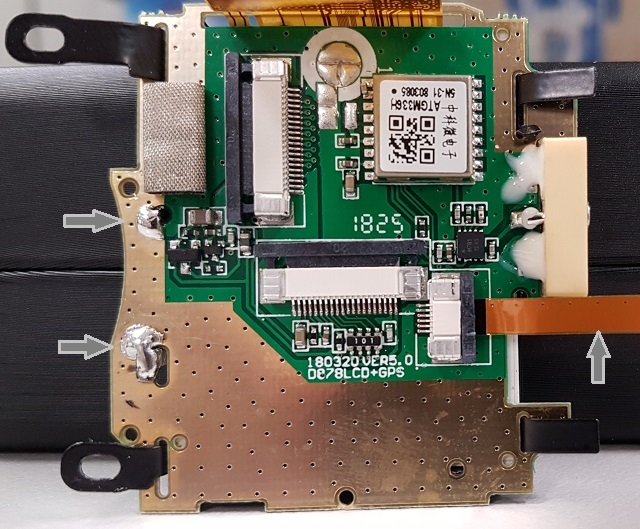
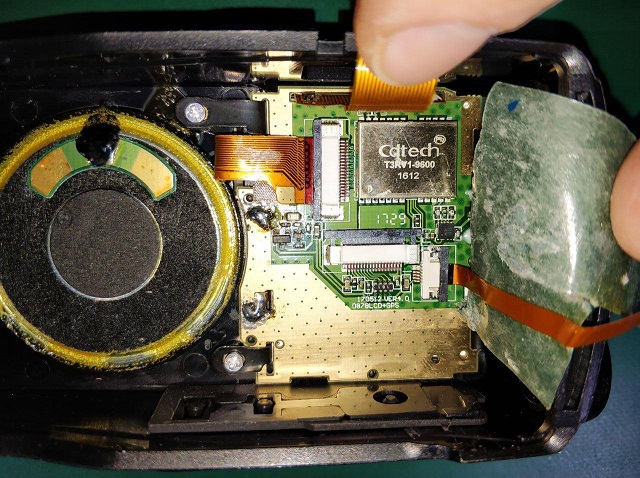
The 878 main board back side, with brass RF shield fitted
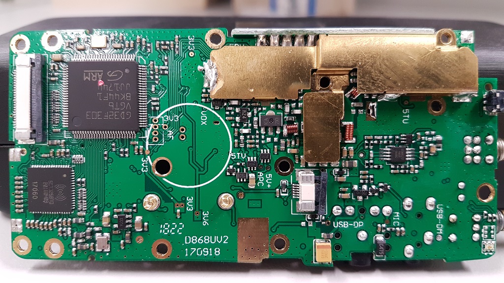
The 878 main board back side, with brass RF shield removed this time
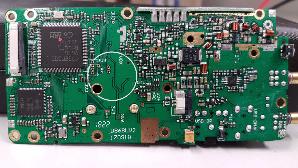
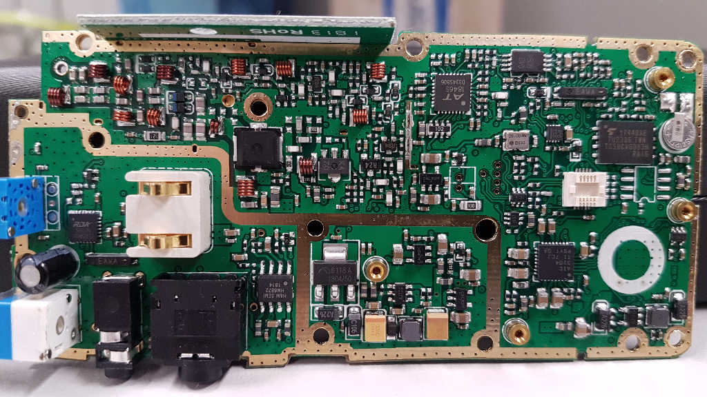
You can download high resolution pictures (7 Mb) of the above from here:
The 878 battery charger:
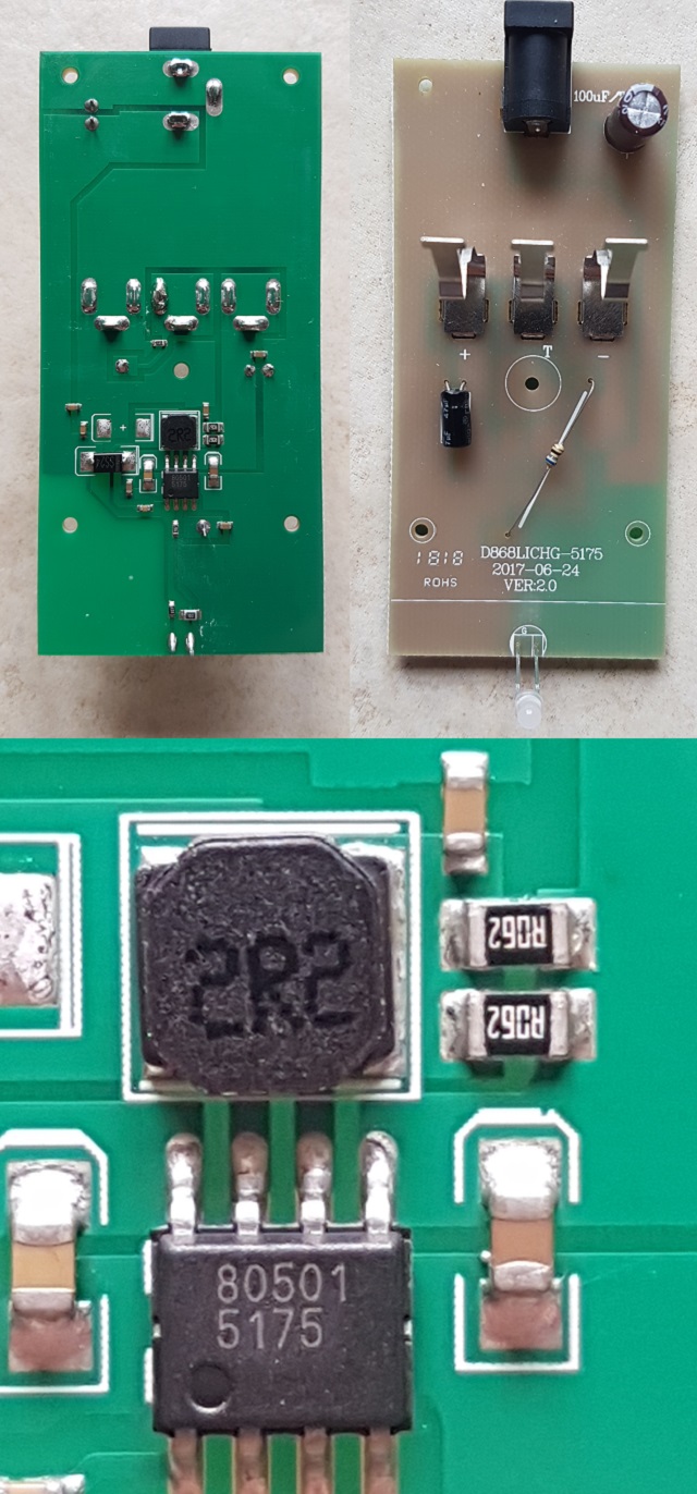
The heart of the charger is a CHK0501 lithium ion charger IC. AnyTone appear to have very recently (early 2020, charger PCB version 4) redesigned the charger base circuitry, and while it still uses the CHK0501 charger IC, it is hoped that these changes may make the charger more reliable. It's too early to say at this stage, time will tell.
- If you don't have any SMD rework tools, an easy way to do this is to use a pair of fine, sharp pointed cutters to snip through the eight legs of the surface mount IC, then desolder the legs from the PCB lands so there is no contact made between the dead IC and the PCB lands
- Optionally, you could then use a pair of needle nose pliers to carefully twist off the IC body off the PCB
- Also make use the same sharp pointed cutters to chomp through the diode and desolder the remains of it.
- The resistors are best removed by adding some quite substantial blobs of solder to both ends of each resistor, then 'laying' your soldering iron tip across the resistor and solder blobs so that both ends are heated at the same time, then quickly move the resistor off it's PCB lands.
- The TP5100 PCB also needs some changes, solder bridge the SET lands, and remove one of the current limiting resistors as shown in step 3
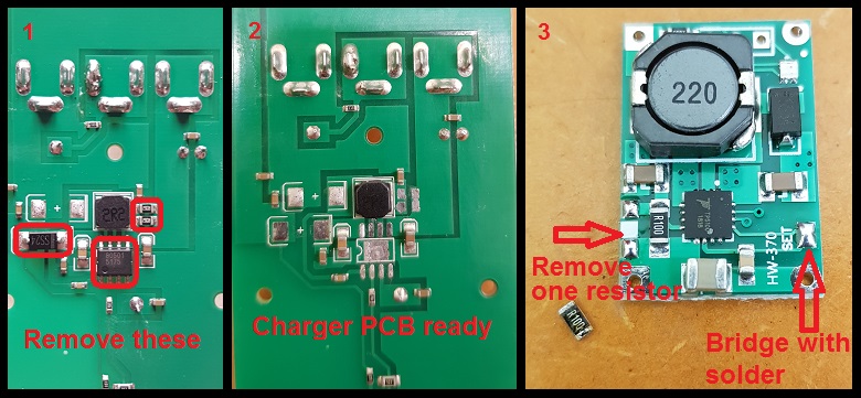
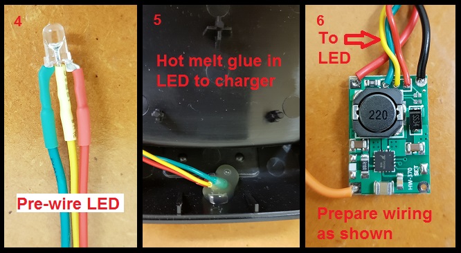
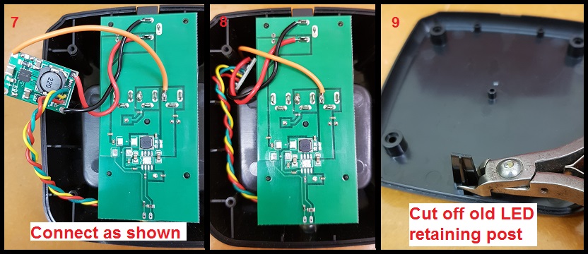
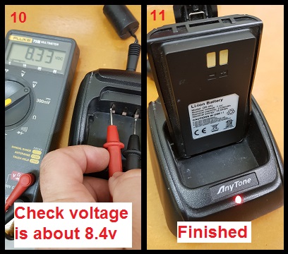
- Charger constantly flashing red-green-red, even without a battery inserted: charger base has failed.
- Radio displays "Checking Flash" or "Bad Block": faulty or corrupt flash memory, can sometimes be fixed with a reset of the radio
- Radio LCD display goes fuzzy or strange during transmit: faulty display or loose connecting ribbon cables - if you are confident enough, try re-seating the ribbon cables and firmly lock their header retainer into place to fix
- Radio freezes on power up: this is sometimes due to the SCT3258 baseband IC going bad, but sometimes can be fixed by the 'defrost' solutions below
General technical information
The 868 / 878 / DMR-6X2 contains the following devices:
- Early 868s: GD32F303VET6 ARM Cortex-M4 32 bit MCU with 512kbyte internal flash and 64kbyte internal SRAM
- Later 868s, 878s and most 6X2: GD32F303VGT6 ARM Cortex-M4 32 bit MCU with 1024kbyte internal flash and 96kbyte internal SRAM
- Toshiba TC58CVG0S3HRAIG 1Gbit / 128Mbyte NAND flash memory
- Sicomm CT3258TD baseband processor for DMR & dPMR with built in AMBE2+ vocoder & 12.2 MHz oscillator
- Texas Instruments TLV320AIC3204 DSP / codec
- AT1846S radio-on-a-chip & 26.0 MHz reference oscillator
- RDA 5802N FM broadcast band receiver
- H&M Semiconductor HM8872 8 watt audio power amp
- Two NXP AFT05MS006NT1 LDMOS 6 watt RF power amps, 18dB narrowband gain, one each for independent VHF & UHF power amp stages
- 2SC3356 based low noise preamps for VHF & UHF receiver stages
- VHF and UHF receive front ends each have four stages of varactor track tuned filtering
- Infineon BGM781N11 GPS front end (GPS models only)
- ATGM336H GPS & BDS (BeiDou) positioning module or Cdtech T3RV1-9600 GPS only module (GPS models only)
- Battery backup for real time clock
- Solder pads for expansion memory SOIC size IC and a small push fit expansion connector for add on Bluetooth or extra memory module. (Not found on the 868 version 1 hardware)
0x08000000 to 0x080FFFFF is mapped to GD32F303VE or GD32F303VG MCU internal flash memory:
- 0x08000000 to 0x08003FFF used by the AnyTone custom boot loader for firmware updating etc.
- 0x08004000 to 0x0807FFFF used by firmware and display fonts
- 0x08080000 to 0x080FFFFF is only available on hardware fitted with GD32F303VG (1024k) MCUs, and is empty on 868s, used by firmware on 878s.
- Reading the flash is perfectly safe, it is the writing of data that you need to be careful with.
- Through careless use when writing data, this software can most definitely 'brick' or disable your radio, or cause hardware damage by writing RF output power values to destructively high levels for example. You accept all risk in use of the software.
- The radio will attempt to prevent overwriting of critical data in certain areas of the flash memory, typically stored between addresses 02F00000 and 02FDFFFF. It is generally better to create a set of CDD, CDI and SPI files to write to this area of memory, and write using icon update mode to ensure the radio MCU is safely halted.
- If using Flash Utility to write to the flash memory you need to apply a (hex) 20000 byte offset. For example, if you want to write to address 00000000 you should instruct Flash Utility to begin writing at 00020000. It is unknown why this is necessary, and exactly at what memory address this offset is no longer needed, but it applies at least as high as address (hex) 04000000.
- You should write to the radio in multiples of 256kbytes, even if you only want to change just one byte. (Do not forget the 128k offset that needs to be applied) This restriction doesn't exist when only reading the flash.
- Download from this webpage here
- Download via Mega
- Download via Google Drive
- Download via Sabercat host
Flash Utility is compatible with the 868, 878 & 6X2. When reading from the radio, it might be a bit confusing to users to have to specify a file before reading begins - this is the file you will be saving your read results to.
- Download & unzip Flash Utility software (10kb) from:
Download from this webpage here
Download via Mega
Download via Google Drive
Download via Sabercat host
- With a fully charged battery, plug in your programming cable to the radio and your computers USB port, and power on the radio
- Start AT_Flash_Utility_v3.exe
- In the Start Address (Hex) box type 2F00000 [ 2F and five zeros ] and in the Length (Hex) box type E0000 [ E and four zeros ]. Take care to correctly enter the hex addresses given in this step.
- Click the Select File button, and navigate to the directory you wish to save the data backup file into. Enter a file name of "myvital.bin" then select Save. If you have more than one radio, or perhaps you own another model of radio, make sure you save each backup to a different directory and clearly identify which individual radio that directory and it's backup file belongs to.
- Select your usual Com Port, and then click the Read button. AT Flash Utility will then read the vital bits of flash memory and save it to a file called myvital.bin and takes about a minute to complete.
- After the read is complete, click on the OK button. Confirm that your myvital.bin file was saved to your directory and that its size is 896kb. If not, go back to step 4 again, making absolutely sure you have given the correct Hex address and length values.
- Close down AT Flash Utility.
- Rename the file myvital.bin to myvital.CDD (i.e. change the file extension from .bin to .CDD) This step is very important, do not skip this step!
- Restoring a saved backup file
This step shouldn't be carried out unless you have strong reason to believe your RF alignment data is corrupt. There is inherent risk, though very slight, that writing data to parts of flash memory that isn't normally user accessible can make things worse. Follow these steps carefully, and take your time.- It is assumed you already have downloaded Flash Utility as per Making a backup step 1 just above.
- Download some supporting files (<1 kb) necessary to restoring a backup from:
Download from this webpage here
Download via Mega
Download via Google Drive
Download via Sabercat host
- Unzip these support files to your directory holding the backup file. You should now have the following files in there: myvital.CDD (your previously saved & renamed myvital.bin), myvital.CDI & myvital.spi
- With a fully charged battery, plug in your programming cable to the radio and your computers USB port, and power on the radio while holding down the PTT & PF2 buttons. Confirm the display shows "UPDATE MODE" with a white background
- In the CPS programming software, go to menu Tool > Firmware and Icon Update. Click on the Open Update File button, navigate to the directory where you saved your backup, select the myvital.spi file and click Open. Click on OK below the File Open Succesed! message. (If you have multiple radios and multiple backup files, make absolutely sure you have selected the correct backup file to send to the connected radio)
- Ensure Duplex box is ticked, and that Com Speed is set to 921600. Click on Write. This step will restore vital RF tuning data that is unique to your radio back in flash memory, and takes 25 seconds to complete.
- Turn the radio off, then power on the radio normally this time, without holding any buttons.
- You may need to set the time & date. The radio might also power up in Chinese language mode, this is OK, after writing your codeplug to the radio that will be corrected. You may need to power up the radio in test mode to change the band (MODE) or set the band with AT Options software to match the band you were using before, if you get Band Error when sending your codeplug back to the radio.
- You are now done!
- You must ensure your CDD file is 256kbyte or some multiple of that size
- You must ensure that your data to be written starts at a 256kbyte page eg: hex addresses 00040000, 00080000, 000C0000, 00100000, 00140000 etc.
- And then lastly, you will write this data with an offset of (hex) 20000 bytes above the intended actual location you wish to write to.
-
- Turn the radio off, leave it off for ten seconds, and turn back on
- Turn the radio off, remove the battery for ten seconds, replace the battery and turn back on
- Attempt a reset: turn the radio off, and then hold PTT and the button immediately below the PTT while turning the radio on (don&'t forget you need to have reset enabled in CPS first)
- Reflash firmware: turn the radio off, hold the PTT and top panel button while turning the radio on. The LED will flash red and you can then use the CPS software to load your firmware file using Tool > Firmware and Icon Update
- Reflash the SCT3258 baseband: Download the SCT3258 software , instructions and baseband files (3.18 Mb) from:
Download via Mega
Download via Google Drive
Note Google has recently tightened security for downloads and this file may or may not be available to download by you entirely at Google's discretion
Download via Sabercat host
To enter the SCT update mode, hold down the top orange / blue button and # keys while turning the radio on. On the DJ-MD5, SCT update mode is entered by holding down PTT + # keys on power up. From there, follow the instructions included in the download to write the latest baseband file V2.01.07BF to the SCT3258.
- Once you have managed to regain control of the radio, the first thing to do is re-build your 'codeplug' to remove any hidden corruption that caused the freeze in the first place. 99.9% of problems encountered are usually the result of poor 'codeplug' practices. Using other people's codeplugs, originating from several CPS versions back, and then added to piecemeal, is almost certain to cause problems. The solution to this is to ensure your codeplug is rebuilt which ensures the underlying data that your codeplug is built upon is fresh and consistent with the CPS and firmware version in use. Do not take any shortcuts in the following process!
- In CPS, load your old saved codeplug and export everything (Tool > Export > Export All)
- Go through all your Optional Setting and write them down or take screen shots of all the settings there. If you are using encryption, also record all your encryption keys. These settings and encryption keys are not saved by the Export All process.
- RESET the radio - this step is very important! If you do not do this, the old & possibly problematic data in the radio is not removed.
- In CPS, read from the freshly reset radio (yes, you are reading a 'blank' radio, that is OK)
- Import everything saved from step 1
- Finish off your codeplug by attending to the Optional Setting & encryption keys if applicable and confirm all is correct
- Send the freshly rebuilt codeplug to the radio
- If you had a custom start up picture or background pictures, send those to the radio now
- Finally, save the rebuilt codeplug and ensure you use this saved file as the basis for any further changes you may make, and make sure you delete your old problematic codeplug file.
If these steps have not worked, there are two procedures that may help un-freeze your radio and get you going again. Note that these defrosters will only work if the freezing is caused by memory corruption. If the problem is a hardware failure, then these will not work.
Quick defroster
Credit to Francesco IK8JHL & Andres CD2KDT
This process is quick and simple, forcing the radio to undergo a reset. You will loose your codeplug, so make sure you have a saved copy first.
- Download the appropriate fast defroster:
878 fast defroster (1 kb):
Download from this webpage here
Download via Mega
Download via Google Drive
Download via Sabercat host
868 fast defroster (1 kb):
Download from this webpage here
Download via Mega
Download via Google Drive
Download via Sabercat host
6X2 fast defroster (1 kb):
Download from this webpage here
Download via Mega
Download via Google Drive
Download via Sabercat host
Alinco DJ-MD5 fast defroster (1 kb):
Download from this webpage here
Download via Mega
Download via Google Drive
Download via Sabercat host
Alinco DJ-MD5X fast defroster (1 kb):
Download from this webpage here
Download via Mega
Download via Google Drive
Download via Sabercat host - Unzip the contents into a new directory
- Confirm that your frozen radio can power up in the Icon Update mode: turn the radio off, hold the PTT & PF2 buttons down while powering on the radio. You should see a white screen with "UPDATE MODE" displayed. If you do not see this screen, this process will not work for you and the radio will have to go back to the supplier for repair or replacement.
- Start up the CPS, preferably using the latest version you can get for your model radio. Go to menu Set > Set Com. Select the Com Port you normally use to program your radio.
- In the CPS, go to menu Tool > Firmware and Icon Update. Click on the Open Update File button, navigate to the working directory and select the Fast-defrost.spi file and click Open. Click on OK below the File Open Succesed! message.
- Ensure Duplex box is ticked, and that Com Speed is set to 921600. Click on Write. The data only takes a fraction of a second to be written to the radio.
- Turn off the radio, wait ten seconds, then turn it back on again. The radio should immediately go through a reset.
- You may need to set the time & date. The radio might also power up in Chinese language mode, this is OK, after writing your codeplug to the radio that will be corrected. You may need to power up the radio in test mode to change the band (MODE) or set the band with AT Options software to match the band you were using before, if you get Band Error when sending your codeplug back to the radio.
- You are now done!
Full defroster
If the above quick defroster didn't work, then you can try using this more comprehensive process to un-freeze your radio. Follow the steps carefully and exactly.
This process will completely erase & over-write your radio flash memory, and you proceed at your own risk. While it has helped un-freeze a couple of 878s, it can not be absolutely guaranteed to work for you. This will also wipe your codeplug, so make sure you have a saved copy somewhere.
-
- Test that your frozen radio can power up in the Icon Update mode: turn the radio off, hold the PTT & PF2 buttons down while powering on the radio. You should see a white screen with "UPDATE MODE" displayed. If you do not see this screen, this process will not work for you.
- Turn the radio off for now, and fully charge the battery
- Download the defrost pack from:
878 full defroster (2.1 Mb):
Download via Mega
Download via Google Drive
Download via Sabercat host
868 full defroster (2.1 Mb):
Download via Mega
Download via Google Drive
Download via Sabercat host
6X2 full defroster (1.8 Mb):
Download via Mega
Download via Google Drive
Download via Sabercat host
Alinco DJ-MD5X full defroster (3.4 Mb):
Download via Mega
Download via Google Drive
Download via Sabercat host
Note: ***NOT*** SUITABLE FOR DJ-MD5T OR DJ-MD5E. This will only work on the DJ-MD5XE / DJ-MD5XT / DJ-MD5XEG / DJ-MD5XTG models. I do not have a full defroster available for the DJ-MD5T / DJ-MD5E models.
- Unzip the contents into a new directory
- With a fully charged battery, plug in your programming cable to the radio and your computers USB port, hold down PTT & PF2 while powering on the radio, and confirm the display shows "UPDATE MODE" with a white background
- Start AT_Flash_Utility_v3.exe In the Start Address (Hex) box type 2F00000 [ 2F and five zeros ] and in the Length (Hex) box type E0000 [ E and four zeros ]. Then click the Select File button, and navigate to the directory you have unzipped the defrosting files into. Enter a file name of "myvital.bin" then select Save.
- Select your usual Com Port, and then click the Read button. You will get two error messages, this is fine, just click on OK. AT Flash Utility will then read some vital flash memory and save it to a file called myvital.bin and takes about 55 seconds to complete.
- After the read is complete, click on the OK button. Confirm that your myvital.bin file is in the working directory and that its size is 896kb. If not, go back to step 6 again, making absolutely sure you have given the correct Hex address and length values.
- Close down AT Flash Utility.
- Rename the file myvital.bin to myvital.CDD (i.e. change the file extension from .bin to .CDD) This step is very important, do not skip this step
- Turn off your radio, and again hold down the PTT & PF2 buttons while powering on. Confirm the display shows "UPDATE MODE" with a white background
- Start up the CPS, preferably using the most current version CPS available for your model. Go to menu Set > Set Com. Select the Com Port you normally use to program your radio.
- In the CPS, go to menu Tool > Firmware and Icon Update. Click on the Open Update File button, navigate to the working directory and select the total flash fresh reset .spi file and click Open. Click on OK below the File Open Succesed! message.
- Ensure Duplex box is ticked, and that Com Speed is set to 921600. Click on Write. This step will totally wipe your flash memory clean, and takes around 40-45 minutes to complete.
- Turn off your radio, and again hold down the PTT & PF2 buttons while powering on. Confirm the display shows "UPDATE MODE" with a white background
- In the CPS, go to menu Tool > Firmware and Icon Update. Click on the Open Update File button, navigate to the working directory and
for 868 users, select the D868_1G_ICON_V1.20_20190226.spi file, click Open
for 878 users, select the D878_1G_ICON_V1.21_20201230.spi file, click Open
6X2 users, your icon file is called DMR_6X2_PIC_V1.1a.spi select it and click Open
and Alinco DJ-MD5 users your icon file is called Alinco_DJMD5XEG_icon_backup.spi
Click on OK below the File Open Succesed! message. - Ensure Duplex box is ticked, and that Com Speed is set to 921600. Click on Write. This step will rebuild icons and text bitmaps in flash memory, and takes 50 seconds to complete.
- Turn off your radio, and yet again hold down the PTT & PF2 buttons while powering on. Confirm the display shows "UPDATE MODE" with a white background
- In the CPS, go to menu Tool > Firmware and Icon Update. Click on the Open Update File button, navigate to the working directory and select the myvital.spi file and click Open. Click on OK below the File Open Succesed! message.
- Ensure Duplex box is ticked, and that Com Speed is set to 921600. Click on Write. This step will restore vital RF tuning data that is unique to your radio back in flash memory, and takes 25 seconds to complete. This is another very important step that you should not skip, otherwise your radio will not properly transmit on DMR.
- Power cycle the radio normally this time, without holding any buttons. It should boot up somewhat normally this time. You may need to set the time & date. The radio might also power up in Chinese language mode, this is OK, after writing your codeplug to the radio that will be corrected. You may need to power up the radio in test mode to change the band (MODE) or set the band with AT Options software to match the band you were using before, if you get Band Error when sending your codeplug back to the radio.
- You are now done!
If these suggestions still do not un-freeze your radio then, sadly, it it likely the problem is a hardware fault, and no amount of resets, reloading of firmware or codeplugs, or performing any special procedure will fix that. You should get in touch with the seller of the radio to discuss repair.
- Rule 1: Rebuild your codeplug
- First make sure your CPS software version matches the firmware version presently in your radio
- In CPS, load your existing configuration codeplug and export everything (Tool > Export > Export All)
- Go through all your Optional Setting and write them down or take screen shots of all the settings there. If you are using encryption, also record all your encryption keys. These settings and encryption keys are not saved by the Export All process.
- RESET the radio - this step is very important! If you do not do this, the old & possibly problematic data in the radio is not removed.
- In CPS, read from the freshly reset radio (yes, you are reading a 'blank' radio, that is OK)
- Import everything saved from step 1
- Finish off your codeplug by attending to the Optional Setting & encryption keys if applicable and confirm all is correct
- Send the freshly rebuilt codeplug to the radio
- If you had a custom start up picture or background pictures, send those to the radio now
- Save the rebuilt codeplug and ensure you use this saved file as the basis for any further changes you may make, and make sure you delete your old problematic codeplug file.
- Ensure you rebuild your codeplug using these steps EVERY time a firmware update is made.
- Rule 2: Turn off GPS
- Rule 3: Turn off Roaming
- Rule 4: Make use of the Data ACK disable feature
- Rule 5: Turn off power save
- Rule 6: Do not use Sub-Channel unless necessary
- Download via Mega
- Download via Google Drive
Note Google has recently tightened security for downloads and this file may or may not be available to download by you entirely at Google's discretion
- Download via Sabercat host
- Exploiting the capabilities of the TLV320AIC3204 audio codec chip. This is a very powerful chip with the possible scope to facilitate DSP noise reduction, equalisation, tone control and digital AGC audio.
- Explore some new fonts, perhaps some screen colour changes and icon customisation
- Patching the vocoder in the SCT3258 for something else entirely. There is a very strong resemblance between AnyTone's SCT3258TD_UpdateFlash_v2_01_05NJ.hex and Hytera's PD36x series SCT3928_UpdateFlash_V2_01_05PD.hex - both in name and hex content. The Hytera can already load different hex files for AMBE, SELP, NVOC & COMM vocoders, but this is slightly dependant on the different hardware installed in the Hytera radios. It would be very interesting to experiment with an open source ham vocoder like FreeDV's Codec2, and see if this could be used to replace the AMBE2+ vocoder in the SCT3258. Sadly the SiComm hex code that gets sent to the SCT3258 is encrypted, so for the moment any patching is unlikely
&© Copyright Jason Reilly, 2018-2022